IBM 6000R Hardware Maintenance Manual - Page 109
Ultra160 SCSI ports, SCSI cabling requirements, Setting SCSI IDs
 |
UPC - 087944534341
View all IBM 6000R manuals
Add to My Manuals
Save this manual to your list of manuals |
Page 109 highlights
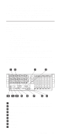
Table 16. Auxiliary-device connector pin-number assignments Pin 1 Data 2 Not connected 3 Ground 4 +5 V dc 5 Clock 6 Not connected Signal Ultra160 SCSI ports The server has an integrated dual-channel Ultra160 small computer system interface (SCSI) controller. This controller supports two independent Ultra 160/m SCSI channels: one internal and one external. Each of these channels supports up to 15 SCSI devices. In addition, this controller uses: • Double-transition clocking to achieve high transfer rates • Domain name validation to negotiate compatible data transfer speeds with each device • Cyclic-redundancy checking (CRC), instead of the usual parity checking, to significantly improve data reliability • An active terminator on the system board for SCSI bus termination The server comes with two SCSI cables. One cable connects the internal SCSI channel connector to the standard hot-swap-drive backplane. The other cable is not connected to the server when the server is shipped and must be installed in the server. If you want to use the external LVD SCSI channel connector to connect external SCSI devices to the server, remove the knockout on the rear of the server and install the LVD SCSI cable that comes with the server. Note: If you install a PCI RAID adapter to configure and manage the internal hot-swap drives, you must move the SCSI cable from the system-board SCSI connector to an internal channel connector on the RAID adapter. See "Cabling example for the ServeRAID adapter" on page 71 for additional information. SCSI cabling requirements If you plan to attach external SCSI devices, you must order additional SCSI cables. To select and order the correct cables for use with external devices, contact your IBM reseller or IBM marketing representative. For information about the maximum length of SCSI cable between the terminated ends of the cable, refer to the ANSI SCSI standards. Adhering to these standards will help ensure that the server operates properly. Setting SCSI IDs Each SCSI device connected to a SCSI controller must have a unique SCSI ID. This ID enables the SCSI controller to identify the device and ensure that different devices on the Installing options 97
-
 1
1 -
2
-
3
-
4
-
5
-
6
-
7
-
8
-
9
-
10
-
11
-
12
-
13
-
14
-
15
-
16
-
17
-
18
-
19
-
20
-
21
-
22
-
23
-
24
-
25
-
26
-
27
-
28
-
29
-
30
-
31
-
32
-
33
-
34
-
35
-
36
-
37
-
38
-
39
-
40
-
41
-
42
-
43
-
44
-
45
-
46
-
47
-
48
-
49
-
50
-
51
-
52
-
53
-
54
-
55
-
56
-
57
-
58
-
59
-
60
-
61
-
62
-
63
-
64
-
65
-
66
-
67
-
68
-
69
-
70
-
71
-
72
-
73
-
74
-
75
-
76
-
77
-
78
-
79
-
80
-
81
-
82
-
83
-
84
-
85
-
86
-
87
-
88
-
89
-
90
-
91
-
92
-
93
-
94
-
95
-
96
-
97
-
98
-
99
-
100
-
101
-
102
-
103
-
 104
104 -
 105
105 -
 106
106 -
 107
107 -
 108
108 -
 109
109 -
 110
110 -
 111
111 -
 112
112 -
 113
113 -
 114
114 -
115
-
116
-
117
-
118
-
119
-
120
-
121
-
122
-
123
-
124
-
125
-
126
-
127
-
128
-
129
-
130
-
131
-
132
-
133
-
134
-
135
-
136
-
137
-
138
-
139
-
140
-
141
-
142
-
143
-
144
-
145
-
146
-
147
-
148
-
149
-
150
-
151
-
152
-
153
-
154
-
155
-
156
-
157
-
158
-
159
-
160
-
161
-
162
-
163
-
164
-
165
-
166
-
167
-
168
-
169
-
170
-
171
-
172
-
173
-
174
-
175
-
176
-
177
-
178
-
179
-
180
-
181
-
182
-
183
-
184
-
185
-
186
-
187
-
188
-
189
-
190
-
191
-
192
-
193
-
194
-
195
-
196
-
197
-
198
-
199
-
200
-
201
-
202
-
203
-
204
-
205
-
206
-
207
-
208
-
209
-
210
-
211
-
212
-
213
-
214
-
215
-
216
-
217
-
218
-
219
-
220
-
221
-
222
-
223
-
224
-
225
-
226
-
227
-
228
-
229
-
230
-
231
-
232
-
233
-
234
-
235
-
236
-
237
-
238
-
239
-
240
-
241
-
242
-
243
-
244
-
245
-
246
-
247
-
248
-
249
-
250
-
251
-
252
 |
 |