IBM 6000R Hardware Maintenance Manual - Page 170
Run Information Panel, Run LED diagnostics.
 |
UPC - 087944534341
View all IBM 6000R manuals
Add to My Manuals
Save this manual to your list of manuals |
Page 170 highlights
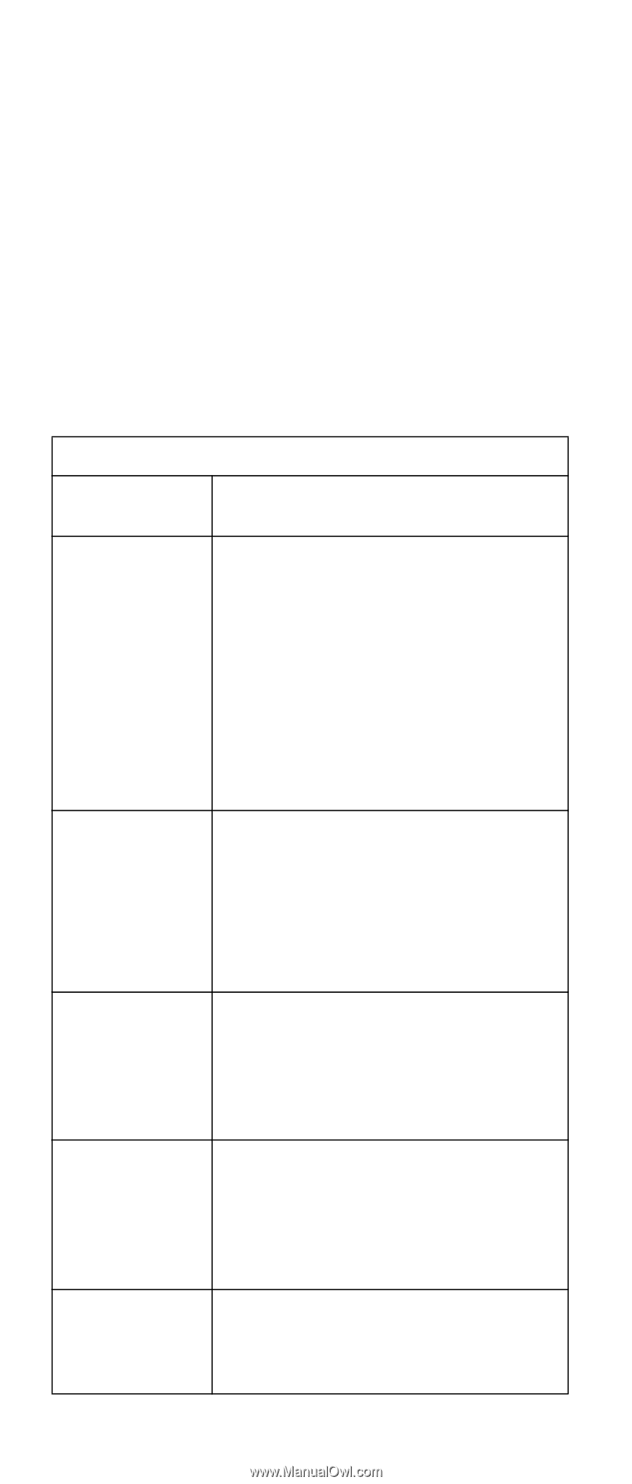
and check the diagnostic panel LEDs. The following is a complete list of diagnostic panel LEDs followed by the FRU/Action for correcting the problem. Note: If a diagnostic panel LED is on and the information LED panel system error LED is off, there is probably an LED problem. Run LED diagnostics. Notes: 1. To locate the LEDs on the system board see "System board component locations" on page 54. 2. Check the System Error Log for additional information before replacing a FRU. 3. It may be necessary to view the System Error Log from a remote connection, such as MOST. 4. The memory card DIMM error LEDs and processor error LEDs turn off when the system is powered down. Note: The System Error LED will also be on. Diagnostic Panel LED FRU/Action All LEDs off (Check System Error Log for error condition, then clear System Error Log when the problem is found.) 1. System Error Log is 75% full; clear the log. 2. Bad, missing or mis-installed processor terminator; remove and reinsert terminator. 3. PFA alert; check Netfinity log for failure; clear PFA alert; remove AC power for at least 20 seconds, reconnect, then power up system. 4. Run Information Panel diagnostics. CPU LED on (The LED next to the failing CPU should be on.) 1. Insure terminator (or processor if multiprocessor system) is installed in slot D. See "Installing a microprocessor kit" on page 81. 2. Processor 1, 2, 3, or 4 3. System Board. DASD LED on (Check amber drive LED for a failing hard drive if RAID system.) 1. Be sure the fans are operating correctly and the air flow is good. 2. Failing drive. 3. SCSI Backplane. FAN LED on 1. Check individual fan LEDs. 2. Replace respective fan. 3. Fan Cable. 4. System Board. 5. Power Backplane Board. MEM LED on (The LED next to the failing DIMM is on.) 1. Failing DIMM(s) in slot J1-J16. 2. Memory Card. 3. System Board. 158 Netfinity 6000R Type 8682 Models 1RY, 2RY
-
 1
1 -
2
-
3
-
4
-
5
-
6
-
7
-
8
-
9
-
10
-
11
-
12
-
13
-
14
-
15
-
16
-
17
-
18
-
19
-
20
-
21
-
22
-
23
-
24
-
25
-
26
-
27
-
28
-
29
-
30
-
31
-
32
-
33
-
34
-
35
-
36
-
37
-
38
-
39
-
40
-
41
-
42
-
43
-
44
-
45
-
46
-
47
-
48
-
49
-
50
-
51
-
52
-
53
-
54
-
55
-
56
-
57
-
58
-
59
-
60
-
61
-
62
-
63
-
64
-
65
-
66
-
67
-
68
-
69
-
70
-
71
-
72
-
73
-
74
-
75
-
76
-
77
-
78
-
79
-
80
-
81
-
82
-
83
-
84
-
85
-
86
-
87
-
88
-
89
-
90
-
91
-
92
-
93
-
94
-
95
-
96
-
97
-
98
-
99
-
100
-
101
-
102
-
103
-
104
-
105
-
106
-
107
-
108
-
109
-
110
-
111
-
112
-
113
-
114
-
115
-
116
-
117
-
118
-
119
-
120
-
121
-
122
-
123
-
124
-
125
-
126
-
127
-
128
-
129
-
130
-
131
-
132
-
133
-
134
-
135
-
136
-
137
-
138
-
139
-
140
-
141
-
142
-
143
-
144
-
145
-
146
-
147
-
148
-
149
-
150
-
151
-
152
-
153
-
154
-
155
-
156
-
157
-
158
-
159
-
160
-
161
-
162
-
163
-
164
-
 165
165 -
 166
166 -
 167
167 -
 168
168 -
 169
169 -
 170
170 -
 171
171 -
 172
172 -
 173
173 -
 174
174 -
 175
175 -
176
-
177
-
178
-
179
-
180
-
181
-
182
-
183
-
184
-
185
-
186
-
187
-
188
-
189
-
190
-
191
-
192
-
193
-
194
-
195
-
196
-
197
-
198
-
199
-
200
-
201
-
202
-
203
-
204
-
205
-
206
-
207
-
208
-
209
-
210
-
211
-
212
-
213
-
214
-
215
-
216
-
217
-
218
-
219
-
220
-
221
-
222
-
223
-
224
-
225
-
226
-
227
-
228
-
229
-
230
-
231
-
232
-
233
-
234
-
235
-
236
-
237
-
238
-
239
-
240
-
241
-
242
-
243
-
244
-
245
-
246
-
247
-
248
-
249
-
250
-
251
-
252
 |
 |