HP Xw460c HP Integrated Lights-Out 2 User Guide for Firmware 1.75 and 1.77 - Page 130
Dynamic power capping for server blades, Field, Possible value, Description
 |
View all HP Xw460c manuals
Add to My Manuals
Save this manual to your list of manuals |
Page 130 highlights
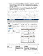
Field Subnet Mask Gateway Domain DNS Server 1 DNS Server 2 DNS Server 3 NTP Server 1 NTP Server 2 Possible value where ### ranges from 0 to 255 where ### ranges from 0 to 255 A character string, including all alphanumeric characters and the dash (-) where ### ranges from 0 to 255 where ### ranges from 0 to 255 where ### ranges from 0 to 255 where ### ranges from 0 to 255 where ### ranges from 0 to 255 Description Subnet mask for the device or interconnect bays Gateway address for the device or interconnect bays The domain name for the device or interconnect bays The IP address for the primary DNS server The IP address for the secondary DNS server The IP address for the tertiary DNS server The IP address of the primary server used to synchronize time and date using the NTP protocol The IP address of the secondary server used to synchronize time and date using the NTP protocol Dynamic power capping for server blades Dynamic power capping is an iLO 2 feature available for c-Class server blades and accessed through HP Onboard Administrator. For more information on all the power setting options for c-Class server blades, see the HP BladeSystem Onboard Administrator User Guide. Dynamic power capping is only available if your system hardware platform, BIOS (ROM), and power micro-controller firmware version support this feature. If your system is capable of performing dynamic power capping, iLO 2 automatically functions in Dynamic Power capping mode. In Onboard Administrator, there are two Dynamic Power capping options: • Dynamic Power If enabled, Dynamic Power automatically places unused power supplies in standby mode to increase enclosure power supply efficiency, thereby minimizing enclosure power consumption during lower power demand. Increased power demands automatically return standby power supplies to full performance. If Dynamic Power is: o Enabled (default setting)-Some power supplies can be automatically placed on standby to increase overall enclosure power subsystem efficiency. o Disabled-All power supplies share the load. The power subsystem efficiency varies based on load. • Enclosure Dynamic Power Cap An optional setting that enables you to set a cap on a group of servers in an enclosure. Set the cap between the values shown above the Enclosure Dynamic Power Cap field. These values are based on the enclosure's current configuration. Using iLO 2 130
-
 1
1 -
2
-
3
-
4
-
5
-
6
-
7
-
8
-
9
-
10
-
11
-
12
-
13
-
14
-
15
-
16
-
17
-
18
-
19
-
20
-
21
-
22
-
23
-
24
-
25
-
26
-
27
-
28
-
29
-
30
-
31
-
32
-
33
-
34
-
35
-
36
-
37
-
38
-
39
-
40
-
41
-
42
-
43
-
44
-
45
-
46
-
47
-
48
-
49
-
50
-
51
-
52
-
53
-
54
-
55
-
56
-
57
-
58
-
59
-
60
-
61
-
62
-
63
-
64
-
65
-
66
-
67
-
68
-
69
-
70
-
71
-
72
-
73
-
74
-
75
-
76
-
77
-
78
-
79
-
80
-
81
-
82
-
83
-
84
-
85
-
86
-
87
-
88
-
89
-
90
-
91
-
92
-
93
-
94
-
95
-
96
-
97
-
98
-
99
-
100
-
101
-
102
-
103
-
104
-
105
-
106
-
107
-
108
-
109
-
110
-
111
-
112
-
113
-
114
-
115
-
116
-
117
-
118
-
119
-
120
-
121
-
122
-
123
-
124
-
 125
125 -
 126
126 -
 127
127 -
 128
128 -
 129
129 -
 130
130 -
 131
131 -
 132
132 -
 133
133 -
 134
134 -
 135
135 -
136
-
137
-
138
-
139
-
140
-
141
-
142
-
143
-
144
-
145
-
146
-
147
-
148
-
149
-
150
-
151
-
152
-
153
-
154
-
155
-
156
-
157
-
158
-
159
-
160
-
161
-
162
-
163
-
164
-
165
-
166
-
167
-
168
-
169
-
170
-
171
-
172
-
173
-
174
-
175
-
176
-
177
-
178
-
179
-
180
-
181
-
182
-
183
-
184
-
185
-
186
-
187
-
188
-
189
-
190
-
191
-
192
-
193
-
194
-
195
-
196
-
197
-
198
-
199
-
200
-
201
-
202
-
203
-
204
-
205
-
206
-
207
-
208
-
209
-
210
-
211
-
212
-
213
-
214
-
215
-
216
-
217
-
218
-
219
-
220
-
221
-
222
-
223
-
224
-
225
-
226
-
227
-
228
-
229
-
230
-
231
-
232
-
233
-
234
-
235
 |
 |