Intel VC820 Design Guide - Page 105
Initial Timing Analysis, Equation 3-1. Setup Time, Equation 3-3. Maximum Flight Time
 |
View all Intel VC820 manuals
Add to My Manuals
Save this manual to your list of manuals |
Page 105 highlights
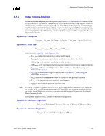
Advanced System Bus Design 3.2.1 Initial Timing Analysis Perform an initial timing analysis of the system using Equation 3-1 and Equation 3-2 shown below. These equations are the basis for timing analysis. To complete the initial timing analysis, values for clock skew and clock jitter are needed, along with the component specifications. These equations contain a multi-bit adjustment factor, MADJ, to account for multi-bit switching effects such as SSO pushout or pull-in that are often hard to simulate. These equations do not take into consideration all signal integrity factors that affect timing. Additional timing margin should be budgeted to allow for these sources of noise. Equation 3-1. Setup Time TCO_MAX + TSU_MIN + CLKSKEW + CLKJITTER + TFLT_MAX + MADJ ≤ Clock Period Equation 3-2. Hold Time TCO_MIN + TFLT_MIN - MADJ ≥ THOLD + CLKSKEW Symbols used in Equation 3-1 and Equation 3-2: - TCO_MAX is the maximum clock to output specification1. - TSU_MIN is the minimum required time specified to setup before the clock1. - CLKJITTER is the maximum clock edge-to-edge variation. - CLKSKEW is the maximum variation between components receiving the same clock edge. - TFLT_MAX is the maximum flight time as defined in Section 3.1, "Terminology and Definitions" on page 3-1. - TFLT_MIN is the minimum flight time as defined in Section 3.1, "Terminology and Definitions" on page 3-1. - MADJ is the multi-bit adjustment factor to account for SSO pushout or pull-in. - TCO_MIN is the minimum clock to output specification1. - THOLD is the minimum specified input hold time. Note: The Clock to Output (TCO) and Setup to Clock (TSU) timings are both measured from the signals last crossing of VREF, with the requirement that the signal does not violate the ringback or edge rate limits. See the respective Processor's datasheet and thePentium® III Processor Developer's Manual for more details. Solving these equations for TFLT results in the following equations: Equation 3-3. Maximum Flight Time TFLT_MAX ≤ Clock Period - TCO_MAX - TSU_MIN - CLKSKEW - CLKJITTER - MADJ Equation 3-4. Minimum Flight Time TFLT_MIN ≥ THOLD + CLKSKEW - TCO_MIN + MADJ Intel®820 Chipset Design Guide 3-5
-
 1
1 -
2
-
3
-
4
-
5
-
6
-
7
-
8
-
9
-
10
-
11
-
12
-
13
-
14
-
15
-
16
-
17
-
18
-
19
-
20
-
21
-
22
-
23
-
24
-
25
-
26
-
27
-
28
-
29
-
30
-
31
-
32
-
33
-
34
-
35
-
36
-
37
-
38
-
39
-
40
-
41
-
42
-
43
-
44
-
45
-
46
-
47
-
48
-
49
-
50
-
51
-
52
-
53
-
54
-
55
-
56
-
57
-
58
-
59
-
60
-
61
-
62
-
63
-
64
-
65
-
66
-
67
-
68
-
69
-
70
-
71
-
72
-
73
-
74
-
75
-
76
-
77
-
78
-
79
-
80
-
81
-
82
-
83
-
84
-
85
-
86
-
87
-
88
-
89
-
90
-
91
-
92
-
93
-
94
-
95
-
96
-
97
-
98
-
99
-
 100
100 -
 101
101 -
 102
102 -
 103
103 -
 104
104 -
 105
105 -
 106
106 -
 107
107 -
 108
108 -
 109
109 -
 110
110 -
111
-
112
-
113
-
114
-
115
-
116
-
117
-
118
-
119
-
120
-
121
-
122
-
123
-
124
-
125
-
126
-
127
-
128
-
129
-
130
-
131
-
132
-
133
-
134
-
135
-
136
-
137
-
138
-
139
-
140
-
141
-
142
-
143
-
144
-
145
-
146
-
147
-
148
-
149
-
150
-
151
-
152
-
153
-
154
-
155
-
156
-
157
-
158
-
159
-
160
-
161
-
162
-
163
-
164
-
165
-
166
-
167
-
168
-
169
-
170
-
171
-
172
-
173
-
174
-
175
-
176
-
177
-
178
-
179
-
180
-
181
-
182
-
183
-
184
-
185
-
186
-
187
-
188
-
189
-
190
-
191
-
192
-
193
-
194
-
195
-
196
-
197
-
198
-
199
-
200
-
201
-
202
-
203
-
204
-
205
-
206
-
207
-
208
-
209
-
210
-
211
-
212
-
213
-
214
-
215
-
216
-
217
-
218
-
219
-
220
-
221
-
222
-
223
-
224
-
225
-
226
-
227
-
228
-
229
-
230
-
231
-
232
-
233
-
234
-
235
-
236
-
237
-
238
-
239
-
240
-
241
-
242
 |
 |
