Intel VC820 Design Guide - Page 122
High Frequency Decoupling, Layer Switch with Multiple Reference Planes
 |
View all Intel VC820 manuals
Add to My Manuals
Save this manual to your list of manuals |
Page 122 highlights
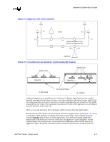
Advanced System Bus Design When routing and stackup constraints require that an AGTL+ signal reference VCC or multiple planes, special care must be given to minimize the SSO impact to timing and noise margin. The best method of reducing adverse effects is to add high-frequency decoupling wherever the transitions occur, as shown in Figure 3-9 and Figure 3-10. Such decoupling should, again, be in the vicinity of the signal transition via and use capacitors with minimal effective series resistance (ESR) and effective series inductance (ESL). When placing the caps it is recommended to space the VSS and VCC vias as close as possible and/or use dual vias since the via inductance may sometimes be higher than the actual capacitor inductance. Figure 3-9. Layer Switch with Multiple Reference Planes Signal Layer A Power Plane Layer Layer Ground Plane Signal Layer B Figure 3-10. One Layer with Multiple Reference Planes Signal Layer A Ground Power 3.4.3.3 High Frequency Decoupling 1l M lt f l d This section contains several high frequency decoupling recommendations that will improve the return path for an AGTL+ signal. These design recommendations will very likely reduce the amount of SSO effects. Just as layer switching and multiple reference planes can create discontinuities in an AGTL+ signal return path, discontinuities may also occur when a signal transitions between the baseboard and cartridge. Therefore, providing adequate high-frequency decoupling across VCCCORE and ground at the SC242 connector interface on the baseboard will minimize the discontinuity in the signal's reference plane at this junction. Note that these additional high-frequency decoupling capacitors are in addition to the high-frequency decoupling already on the processor. Transmission line geometry also influences the return path of the reference plane. The following are decoupling recommendations that take this into consideration: • A signal that transitions from a stripline to another stripline should have close proximity decoupling between all four reference planes. • A signal that transitions from a stripline to a microstrip (or vice versa) should have close proximity decoupling between the three reference planes. • A signal that transitions from a stripline or microstrip through vias or pins to a component (Intel 82820 MCH, etc.) should have close proximity decoupling across all involved reference planes to ground for the device. 3-22 Intel®820 Chipset Design Guide
-
 1
1 -
2
-
3
-
4
-
5
-
6
-
7
-
8
-
9
-
10
-
11
-
12
-
13
-
14
-
15
-
16
-
17
-
18
-
19
-
20
-
21
-
22
-
23
-
24
-
25
-
26
-
27
-
28
-
29
-
30
-
31
-
32
-
33
-
34
-
35
-
36
-
37
-
38
-
39
-
40
-
41
-
42
-
43
-
44
-
45
-
46
-
47
-
48
-
49
-
50
-
51
-
52
-
53
-
54
-
55
-
56
-
57
-
58
-
59
-
60
-
61
-
62
-
63
-
64
-
65
-
66
-
67
-
68
-
69
-
70
-
71
-
72
-
73
-
74
-
75
-
76
-
77
-
78
-
79
-
80
-
81
-
82
-
83
-
84
-
85
-
86
-
87
-
88
-
89
-
90
-
91
-
92
-
93
-
94
-
95
-
96
-
97
-
98
-
99
-
100
-
101
-
102
-
103
-
104
-
105
-
106
-
107
-
108
-
109
-
110
-
111
-
112
-
113
-
114
-
115
-
116
-
 117
117 -
 118
118 -
 119
119 -
 120
120 -
 121
121 -
 122
122 -
 123
123 -
 124
124 -
 125
125 -
 126
126 -
 127
127 -
128
-
129
-
130
-
131
-
132
-
133
-
134
-
135
-
136
-
137
-
138
-
139
-
140
-
141
-
142
-
143
-
144
-
145
-
146
-
147
-
148
-
149
-
150
-
151
-
152
-
153
-
154
-
155
-
156
-
157
-
158
-
159
-
160
-
161
-
162
-
163
-
164
-
165
-
166
-
167
-
168
-
169
-
170
-
171
-
172
-
173
-
174
-
175
-
176
-
177
-
178
-
179
-
180
-
181
-
182
-
183
-
184
-
185
-
186
-
187
-
188
-
189
-
190
-
191
-
192
-
193
-
194
-
195
-
196
-
197
-
198
-
199
-
200
-
201
-
202
-
203
-
204
-
205
-
206
-
207
-
208
-
209
-
210
-
211
-
212
-
213
-
214
-
215
-
216
-
217
-
218
-
219
-
220
-
221
-
222
-
223
-
224
-
225
-
226
-
227
-
228
-
229
-
230
-
231
-
232
-
233
-
234
-
235
-
236
-
237
-
238
-
239
-
240
-
241
-
242
 |
 |
