Intel VC820 Design Guide - Page 47
Length Matching Methods, RSL Signal Layer Alternation
 |
View all Intel VC820 manuals
Add to My Manuals
Save this manual to your list of manuals |
Page 47 highlights
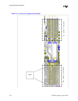
Layout/Routing Guidelines Figure 2-22. RSL Signal Layer Alternation Signal on Secondary Side Signal on Primary Side MCH Signal A Signal B Signal A Route on EITHER layer. Ground Isolation is REQUIRED! Term Signal B Table 2-4. RSL Routing Layer Requirements MCH to 1st RIMM Method 1 Method 2 Primary Side Secondary Side 1st RIMM to 2nd RIMM Secondary Side Primary Side 2.6.2.6 Length Matching Methods In order to allow for greater routing flexibility, the RSL signals require pad-to-pin length matching between the MCH and the first connector. If the trace lengths are matched between the balls of the MCH and the pin of RIMM connector, the length mismatch between the pad (on the die) and the ball has not been accounted. However, given the package dimension, a representation of the length from the pad to the ball, the routing can compensate for this package mismatch. Therefore, the board length mismatch can be increased. The RSL channel requires matching trace lengths from pad-to-pin within ±10 mils. Given these definitions: • Package Dimension: a representation of the length from the pad to the ball. • Board Trace Length: the trace length on the board. • Nominal RSL Length: the length to which all signals are matched. (note: there is not necessarily a trace that is EXACTLY to nominal length, but all RSL signals must be matched to within ±10mil of a nominal length). The Nominal RSL Length is an arbitrary length (within the limits of the routing guidelines) to which all the RSL signals will be matched (within 10 mils). ALL RSL signals must meet the following equation. Intel®820 Chipset Design Guide 2-21
-
 1
1 -
2
-
3
-
4
-
5
-
6
-
7
-
8
-
9
-
10
-
11
-
12
-
13
-
14
-
15
-
16
-
17
-
18
-
19
-
20
-
21
-
22
-
23
-
24
-
25
-
26
-
27
-
28
-
29
-
30
-
31
-
32
-
33
-
34
-
35
-
36
-
37
-
38
-
39
-
40
-
41
-
 42
42 -
 43
43 -
 44
44 -
 45
45 -
 46
46 -
 47
47 -
 48
48 -
 49
49 -
 50
50 -
 51
51 -
 52
52 -
53
-
54
-
55
-
56
-
57
-
58
-
59
-
60
-
61
-
62
-
63
-
64
-
65
-
66
-
67
-
68
-
69
-
70
-
71
-
72
-
73
-
74
-
75
-
76
-
77
-
78
-
79
-
80
-
81
-
82
-
83
-
84
-
85
-
86
-
87
-
88
-
89
-
90
-
91
-
92
-
93
-
94
-
95
-
96
-
97
-
98
-
99
-
100
-
101
-
102
-
103
-
104
-
105
-
106
-
107
-
108
-
109
-
110
-
111
-
112
-
113
-
114
-
115
-
116
-
117
-
118
-
119
-
120
-
121
-
122
-
123
-
124
-
125
-
126
-
127
-
128
-
129
-
130
-
131
-
132
-
133
-
134
-
135
-
136
-
137
-
138
-
139
-
140
-
141
-
142
-
143
-
144
-
145
-
146
-
147
-
148
-
149
-
150
-
151
-
152
-
153
-
154
-
155
-
156
-
157
-
158
-
159
-
160
-
161
-
162
-
163
-
164
-
165
-
166
-
167
-
168
-
169
-
170
-
171
-
172
-
173
-
174
-
175
-
176
-
177
-
178
-
179
-
180
-
181
-
182
-
183
-
184
-
185
-
186
-
187
-
188
-
189
-
190
-
191
-
192
-
193
-
194
-
195
-
196
-
197
-
198
-
199
-
200
-
201
-
202
-
203
-
204
-
205
-
206
-
207
-
208
-
209
-
210
-
211
-
212
-
213
-
214
-
215
-
216
-
217
-
218
-
219
-
220
-
221
-
222
-
223
-
224
-
225
-
226
-
227
-
228
-
229
-
230
-
231
-
232
-
233
-
234
-
235
-
236
-
237
-
238
-
239
-
240
-
241
-
242
 |
 |
