Intel VC820 Design Guide - Page 121
Reference Planes and PCB Stackup
 |
View all Intel VC820 manuals
Add to My Manuals
Save this manual to your list of manuals |
Page 121 highlights
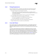
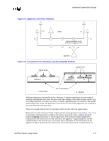
Advanced System Bus Design change the impedance of adjacent trace layers. (For instance, the impedance calculations may have been done for microstrip geometry, and adding a partial plane on the other side of the trace layer may turn the microstrip into a stripline.) 3.4.3.2 Reference Planes and PCB Stackup It is strongly recommended that baseboard stackup be arranged such that AGTL+ signals are referenced to a ground (VSS) plane, and that the AGTL+ signals do not traverse multiple signal layers. Deviating from either guideline can create discontinuities in the signal's return path that can lead to large SSO effects that degrade timing and noise margin. Designing an AGTL+ platform incorporating discontinuities will expose the platform to a risk that is very hard to predict in prelayout simulation. Figure 3-6 shows the ideal case where a particular signal is routed entirely within the same signal layer, with a ground layer as the single reference plane. Figure 3-6. One Signal Layer and One Reference Plane Signal Layer A Ground Plane 1lay 1ref plane vsd When it is not possible to route the entire AGTL+ signal on a single VSS referenced layer, there are methods to reduce the effects of layer switches. The best alternative is to allow the signals to change layers while staying referenced to the same plane (see Figure 3-7). Figure 3-8 shows another method of minimizing layer switch discontinuities, but may be less effective than Figure 3-7. In this case, the signal still references the same type of reference plane (ground). In such a case, it is important to stitch (i.e., connect) the two ground planes together with vias in the vicinity of the signal transition via. Figure 3-7. Layer Switch with One Reference Plane Signal Layer A Ground Plane Signal Layer B l 1 fl d Figure 3-8. Layer Switch with Multiple Reference Planes (same type) Signal Layer A Ground Plane Layer Layer Ground Plane Signal Layer B l M lt f l d Intel®820 Chipset Design Guide 3-21
-
 1
1 -
2
-
3
-
4
-
5
-
6
-
7
-
8
-
9
-
10
-
11
-
12
-
13
-
14
-
15
-
16
-
17
-
18
-
19
-
20
-
21
-
22
-
23
-
24
-
25
-
26
-
27
-
28
-
29
-
30
-
31
-
32
-
33
-
34
-
35
-
36
-
37
-
38
-
39
-
40
-
41
-
42
-
43
-
44
-
45
-
46
-
47
-
48
-
49
-
50
-
51
-
52
-
53
-
54
-
55
-
56
-
57
-
58
-
59
-
60
-
61
-
62
-
63
-
64
-
65
-
66
-
67
-
68
-
69
-
70
-
71
-
72
-
73
-
74
-
75
-
76
-
77
-
78
-
79
-
80
-
81
-
82
-
83
-
84
-
85
-
86
-
87
-
88
-
89
-
90
-
91
-
92
-
93
-
94
-
95
-
96
-
97
-
98
-
99
-
100
-
101
-
102
-
103
-
104
-
105
-
106
-
107
-
108
-
109
-
110
-
111
-
112
-
113
-
114
-
115
-
 116
116 -
 117
117 -
 118
118 -
 119
119 -
 120
120 -
 121
121 -
 122
122 -
 123
123 -
 124
124 -
 125
125 -
 126
126 -
127
-
128
-
129
-
130
-
131
-
132
-
133
-
134
-
135
-
136
-
137
-
138
-
139
-
140
-
141
-
142
-
143
-
144
-
145
-
146
-
147
-
148
-
149
-
150
-
151
-
152
-
153
-
154
-
155
-
156
-
157
-
158
-
159
-
160
-
161
-
162
-
163
-
164
-
165
-
166
-
167
-
168
-
169
-
170
-
171
-
172
-
173
-
174
-
175
-
176
-
177
-
178
-
179
-
180
-
181
-
182
-
183
-
184
-
185
-
186
-
187
-
188
-
189
-
190
-
191
-
192
-
193
-
194
-
195
-
196
-
197
-
198
-
199
-
200
-
201
-
202
-
203
-
204
-
205
-
206
-
207
-
208
-
209
-
210
-
211
-
212
-
213
-
214
-
215
-
216
-
217
-
218
-
219
-
220
-
221
-
222
-
223
-
224
-
225
-
226
-
227
-
228
-
229
-
230
-
231
-
232
-
233
-
234
-
235
-
236
-
237
-
238
-
239
-
240
-
241
-
242
 |
 |
