Intel VC820 Design Guide - Page 109
Monte Carlo Analysis, 3.2.3.4 Simulation Criteria, both fast and slow corner conditions
 |
View all Intel VC820 manuals
Add to My Manuals
Save this manual to your list of manuals |
Page 109 highlights
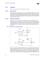
Advanced System Bus Design 3.2.3.3 3.2.3.4 Monte Carlo Analysis Perform a Monte Carlo analysis to refine the passing solution space region. A Monte Carlo analysis involves randomly varying parameters (independent of one another) over their tolerance range. This analysis intends to ensure that no regions of failing flight time and signal quality exists between the extreme corner cases run in pre-layout simulations. For the example topology, vary the following parameters during Monte Carlo simulations: • Lengths L1 through L3 • Termination resistance RTT on the processor cartridge #1 • Termination resistance RTT on the processor cartridge #2 • Z0 of traces on processor cartridge #1 • Z0 of traces on processor cartridge #2 • S0 of traces on processor cartridge #1 • S0 of traces on processor cartridge #2 • Z0 of traces on baseboard • S0 of traces on baseboard • Fast and slow corner processor I/O buffer models for cartridge #1 • Fast and slow corner processor I/O buffer models for cartridge #2 • Fast and slow package models for processor cartridge #1 • Fast and slow package models for processor cartridge #2 • Fast and slow corner 82820 MCH I/O buffer models • Fast and slow 82820 MCH package models Simulation Criteria Accurate simulations require that the actual range of parameters be used in the simulations. Intel has consistently measured the cross-sectional resistivity of the PCB copper to be approximately 1 Ω*mil2/inch, not the 0.662 Ω*mil2/inch value for annealed copper that is published in reference material. Using the 1 Ω*mil2/inch value may increase the accuracy of lossy simulations. Positioning drivers with faster edges closer to the middle of the network typically results in more noise than positioning them towards the ends. However, Intel has shown that drivers located in all positions (given appropriate variations in the other network parameters) can generate the worstcase noise margin. Therefore, Intel recommends simulating the networks from all driver locations, and analyzing each receiver for each possible driver. Analysis has shown that both fast and slow corner conditions must be run for both rising and falling edge transitions. The fast corner is needed because the fast edge rate creates the most noise. The slow corner is needed because the buffer's drive capability will be a minimum, causing the VOL to shift up, which may cause the noise from the slower edge to exceed the available budget. Slow corner models may produce minimum flight time violations on rising edges if the transition starts from a higher VOL. So, Intel highly recommends checking for minimum and maximum flight time violations with both the fast and slow corner models. The fast and slow corner I/O buffer models are contained in the processor and Intel 820 chipset electronic models provided by Intel. The transmission line package models must be inserted between the output of the buffer and the net it is driving. Likewise, the package model must also be placed between a net and the input of a receiver model. Editing the simulator's net description or topology file generally does this. Intel®820 Chipset Design Guide 3-9
-
 1
1 -
2
-
3
-
4
-
5
-
6
-
7
-
8
-
9
-
10
-
11
-
12
-
13
-
14
-
15
-
16
-
17
-
18
-
19
-
20
-
21
-
22
-
23
-
24
-
25
-
26
-
27
-
28
-
29
-
30
-
31
-
32
-
33
-
34
-
35
-
36
-
37
-
38
-
39
-
40
-
41
-
42
-
43
-
44
-
45
-
46
-
47
-
48
-
49
-
50
-
51
-
52
-
53
-
54
-
55
-
56
-
57
-
58
-
59
-
60
-
61
-
62
-
63
-
64
-
65
-
66
-
67
-
68
-
69
-
70
-
71
-
72
-
73
-
74
-
75
-
76
-
77
-
78
-
79
-
80
-
81
-
82
-
83
-
84
-
85
-
86
-
87
-
88
-
89
-
90
-
91
-
92
-
93
-
94
-
95
-
96
-
97
-
98
-
99
-
100
-
101
-
102
-
103
-
 104
104 -
 105
105 -
 106
106 -
 107
107 -
 108
108 -
 109
109 -
 110
110 -
 111
111 -
 112
112 -
 113
113 -
 114
114 -
115
-
116
-
117
-
118
-
119
-
120
-
121
-
122
-
123
-
124
-
125
-
126
-
127
-
128
-
129
-
130
-
131
-
132
-
133
-
134
-
135
-
136
-
137
-
138
-
139
-
140
-
141
-
142
-
143
-
144
-
145
-
146
-
147
-
148
-
149
-
150
-
151
-
152
-
153
-
154
-
155
-
156
-
157
-
158
-
159
-
160
-
161
-
162
-
163
-
164
-
165
-
166
-
167
-
168
-
169
-
170
-
171
-
172
-
173
-
174
-
175
-
176
-
177
-
178
-
179
-
180
-
181
-
182
-
183
-
184
-
185
-
186
-
187
-
188
-
189
-
190
-
191
-
192
-
193
-
194
-
195
-
196
-
197
-
198
-
199
-
200
-
201
-
202
-
203
-
204
-
205
-
206
-
207
-
208
-
209
-
210
-
211
-
212
-
213
-
214
-
215
-
216
-
217
-
218
-
219
-
220
-
221
-
222
-
223
-
224
-
225
-
226
-
227
-
228
-
229
-
230
-
231
-
232
-
233
-
234
-
235
-
236
-
237
-
238
-
239
-
240
-
241
-
242
 |
 |
