Intel VC820 Design Guide - Page 116
Timing Requirements, 3.3.3 Cross-talk Theory,
 |
View all Intel VC820 manuals
Add to My Manuals
Save this manual to your list of manuals |
Page 116 highlights
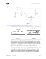
Advanced System Bus Design 3.3.2 3.3.3 Timing Requirements The system timing for AGTL+ is dependent on many things. Each of the following elements combine to determine the maximum and minimum frequency the AGTL+ bus can support: • The range of timings for each of the agents in the system. - Clock to output [TCO]. (Note that the system load is likely to be different from the "specification" load therefore the TCO observed in the system might not be the same as the TCO from the specification.) - The minimum required setup time to clock [TSU_MIN] for each receiving agent. • The range of flight time between each component. This includes: - The velocity of propagation for the loaded printed circuit board [SEFF]. - The board loading impact on the effective TCO in the system. • The amount of skew and jitter in the system clock generation and distribution. • Changes in flight time due to cross-talk, noise, and other effects. Cross-talk Theory AGTL+ signals swing across a smaller voltage range and have a correspondingly smaller noise margin than technologies that have traditionally been used in personal computer designs. This requires that designers using AGTL+ be more aware of cross-talk than they may have been in past designs. Cross-talk is caused through capacitive and inductive coupling between networks. Cross-talk appears as both backward cross-talk and as forward cross-talk. Backward cross-talk creates an induced signal on a victim network that propagates in a direction opposite that of the aggressor's signal. Forward cross-talk creates a signal that propagates in the same direction as the aggressor's signal. On the AGTL+ bus, a driver on the aggressor network is not at the end of the network; therefore it sends signals in both directions on the aggressor's network. Figure 3-4 shows a driver on the aggressor network and a receiver on the victim network that are not at the ends of the network. The signal propagating in each direction causes cross-talk on the victim network. 3-16 Intel®820 Chipset Design Guide
-
 1
1 -
2
-
3
-
4
-
5
-
6
-
7
-
8
-
9
-
10
-
11
-
12
-
13
-
14
-
15
-
16
-
17
-
18
-
19
-
20
-
21
-
22
-
23
-
24
-
25
-
26
-
27
-
28
-
29
-
30
-
31
-
32
-
33
-
34
-
35
-
36
-
37
-
38
-
39
-
40
-
41
-
42
-
43
-
44
-
45
-
46
-
47
-
48
-
49
-
50
-
51
-
52
-
53
-
54
-
55
-
56
-
57
-
58
-
59
-
60
-
61
-
62
-
63
-
64
-
65
-
66
-
67
-
68
-
69
-
70
-
71
-
72
-
73
-
74
-
75
-
76
-
77
-
78
-
79
-
80
-
81
-
82
-
83
-
84
-
85
-
86
-
87
-
88
-
89
-
90
-
91
-
92
-
93
-
94
-
95
-
96
-
97
-
98
-
99
-
100
-
101
-
102
-
103
-
104
-
105
-
106
-
107
-
108
-
109
-
110
-
 111
111 -
 112
112 -
 113
113 -
 114
114 -
 115
115 -
 116
116 -
 117
117 -
 118
118 -
 119
119 -
 120
120 -
 121
121 -
122
-
123
-
124
-
125
-
126
-
127
-
128
-
129
-
130
-
131
-
132
-
133
-
134
-
135
-
136
-
137
-
138
-
139
-
140
-
141
-
142
-
143
-
144
-
145
-
146
-
147
-
148
-
149
-
150
-
151
-
152
-
153
-
154
-
155
-
156
-
157
-
158
-
159
-
160
-
161
-
162
-
163
-
164
-
165
-
166
-
167
-
168
-
169
-
170
-
171
-
172
-
173
-
174
-
175
-
176
-
177
-
178
-
179
-
180
-
181
-
182
-
183
-
184
-
185
-
186
-
187
-
188
-
189
-
190
-
191
-
192
-
193
-
194
-
195
-
196
-
197
-
198
-
199
-
200
-
201
-
202
-
203
-
204
-
205
-
206
-
207
-
208
-
209
-
210
-
211
-
212
-
213
-
214
-
215
-
216
-
217
-
218
-
219
-
220
-
221
-
222
-
223
-
224
-
225
-
226
-
227
-
228
-
229
-
230
-
231
-
232
-
233
-
234
-
235
-
236
-
237
-
238
-
239
-
240
-
241
-
242
 |
 |
