Intel VC820 Design Guide - Page 37
RSL Termination, Secondary Side RSL Breakout Example - ram
 |
View all Intel VC820 manuals
Add to My Manuals
Save this manual to your list of manuals |
Page 37 highlights
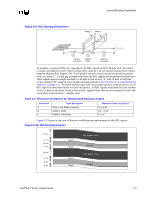
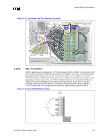
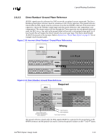
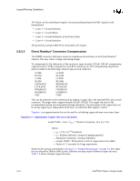
Figure 2-12. Secondary Side RSL Breakout Example Layout/Routing Guidelines 2.6.2.2 RSL Termination All RSL signals must be terminated to 1.8V (Vterm) using 27Ω-2% or 28Ω-1% resistors at the end of the channel opposite the MCH. Resistor packs are acceptable. Vterm must be decoupled using high speed bypass capacitors (one 0.1 µF ceramic chip capacitor per two RSL lines) near the terminating resistors. Additionally, bulk capacitance is required. Assuming a linear regulator with approximate 20 ms response time, two 100 µF tantalum capacitors are recommended. The trace length between the last RIMM and the termination resistors should be less than 3". Length matching in this section of the channel is not required. The Vterm power island should be at LEAST 50 mils wide. This voltage does not need to be supplied during suspend-to-RAM. Figure 2-13. Direct RDRAM Termination Terminator R-packs RSL Signals Vterm Intel®820 Chipset Design Guide 2-11
-
 1
1 -
2
-
3
-
4
-
5
-
6
-
7
-
8
-
9
-
10
-
11
-
12
-
13
-
14
-
15
-
16
-
17
-
18
-
19
-
20
-
21
-
22
-
23
-
24
-
25
-
26
-
27
-
28
-
29
-
30
-
31
-
 32
32 -
 33
33 -
 34
34 -
 35
35 -
 36
36 -
 37
37 -
 38
38 -
 39
39 -
 40
40 -
 41
41 -
 42
42 -
43
-
44
-
45
-
46
-
47
-
48
-
49
-
50
-
51
-
52
-
53
-
54
-
55
-
56
-
57
-
58
-
59
-
60
-
61
-
62
-
63
-
64
-
65
-
66
-
67
-
68
-
69
-
70
-
71
-
72
-
73
-
74
-
75
-
76
-
77
-
78
-
79
-
80
-
81
-
82
-
83
-
84
-
85
-
86
-
87
-
88
-
89
-
90
-
91
-
92
-
93
-
94
-
95
-
96
-
97
-
98
-
99
-
100
-
101
-
102
-
103
-
104
-
105
-
106
-
107
-
108
-
109
-
110
-
111
-
112
-
113
-
114
-
115
-
116
-
117
-
118
-
119
-
120
-
121
-
122
-
123
-
124
-
125
-
126
-
127
-
128
-
129
-
130
-
131
-
132
-
133
-
134
-
135
-
136
-
137
-
138
-
139
-
140
-
141
-
142
-
143
-
144
-
145
-
146
-
147
-
148
-
149
-
150
-
151
-
152
-
153
-
154
-
155
-
156
-
157
-
158
-
159
-
160
-
161
-
162
-
163
-
164
-
165
-
166
-
167
-
168
-
169
-
170
-
171
-
172
-
173
-
174
-
175
-
176
-
177
-
178
-
179
-
180
-
181
-
182
-
183
-
184
-
185
-
186
-
187
-
188
-
189
-
190
-
191
-
192
-
193
-
194
-
195
-
196
-
197
-
198
-
199
-
200
-
201
-
202
-
203
-
204
-
205
-
206
-
207
-
208
-
209
-
210
-
211
-
212
-
213
-
214
-
215
-
216
-
217
-
218
-
219
-
220
-
221
-
222
-
223
-
224
-
225
-
226
-
227
-
228
-
229
-
230
-
231
-
232
-
233
-
234
-
235
-
236
-
237
-
238
-
239
-
240
-
241
-
242
 |
 |
