Intel VC820 Design Guide - Page 96
RTC External RTCRST Circuit, 2.20.6 RTC Routing Guidelines
 |
View all Intel VC820 manuals
Add to My Manuals
Save this manual to your list of manuals |
Page 96 highlights
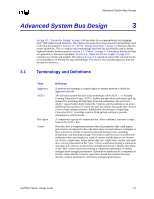
Layout/Routing Guidelines 2.20.5 RTC External RTCRST Circuit The ICH RTC requires some additional external circuitry. The RTCRST# signal is used to reset the RTC well. The external capacitor and the external resistor between RTCRST# and the RTC battery (Vbat) were selected to create an RC time delay, such that RTCRST# will go high some time after the battery voltage is valid. The RC time delay should be in the range of 10-20 ms. When RTCRST# is asserted, bit 2 (RTC_PWR_STS) in the GEN_PMCON_3 (General PM Configuration 3) register is set to 1, and remains set until software clears it. As a result of this, when the system boots, the BIOS knows that the RTC battery has been removed. Figure 2-58. RTCRST External Circuit for the ICH RTC VCC3_3SBY Diode/ Battery Circuit 1K VccRTC 1.0 uF 8.2K RTCRST Circuit RTCRST# 2.2 uF 2.20.6 This RTCRST# circuit is combined with the diode circuit (Figure 2-57) which allows the RTC well to be powered by the battery when the system power is not available. Figure 2-56 is an example of this circuitry that is used in conjuction with the external diode circuit. RTC Routing Guidelines • All RTC OSC signals (RTCX1, RTCX2, VBIAS) should all be routed with trace lengths of less than 1", the shorter the better • Minimize the capacitance between RTCX1 and RTCX2 in the routing (optimal would be a ground line between them) • Put a ground plane under all of the external RTC circuitry • Do not route any switching signals under the external components (unless on the other side of the ground plane) 2-70 Intel®820 Chipset Design Guide
-
 1
1 -
2
-
3
-
4
-
5
-
6
-
7
-
8
-
9
-
10
-
11
-
12
-
13
-
14
-
15
-
16
-
17
-
18
-
19
-
20
-
21
-
22
-
23
-
24
-
25
-
26
-
27
-
28
-
29
-
30
-
31
-
32
-
33
-
34
-
35
-
36
-
37
-
38
-
39
-
40
-
41
-
42
-
43
-
44
-
45
-
46
-
47
-
48
-
49
-
50
-
51
-
52
-
53
-
54
-
55
-
56
-
57
-
58
-
59
-
60
-
61
-
62
-
63
-
64
-
65
-
66
-
67
-
68
-
69
-
70
-
71
-
72
-
73
-
74
-
75
-
76
-
77
-
78
-
79
-
80
-
81
-
82
-
83
-
84
-
85
-
86
-
87
-
88
-
89
-
90
-
 91
91 -
 92
92 -
 93
93 -
 94
94 -
 95
95 -
 96
96 -
 97
97 -
 98
98 -
 99
99 -
 100
100 -
 101
101 -
102
-
103
-
104
-
105
-
106
-
107
-
108
-
109
-
110
-
111
-
112
-
113
-
114
-
115
-
116
-
117
-
118
-
119
-
120
-
121
-
122
-
123
-
124
-
125
-
126
-
127
-
128
-
129
-
130
-
131
-
132
-
133
-
134
-
135
-
136
-
137
-
138
-
139
-
140
-
141
-
142
-
143
-
144
-
145
-
146
-
147
-
148
-
149
-
150
-
151
-
152
-
153
-
154
-
155
-
156
-
157
-
158
-
159
-
160
-
161
-
162
-
163
-
164
-
165
-
166
-
167
-
168
-
169
-
170
-
171
-
172
-
173
-
174
-
175
-
176
-
177
-
178
-
179
-
180
-
181
-
182
-
183
-
184
-
185
-
186
-
187
-
188
-
189
-
190
-
191
-
192
-
193
-
194
-
195
-
196
-
197
-
198
-
199
-
200
-
201
-
202
-
203
-
204
-
205
-
206
-
207
-
208
-
209
-
210
-
211
-
212
-
213
-
214
-
215
-
216
-
217
-
218
-
219
-
220
-
221
-
222
-
223
-
224
-
225
-
226
-
227
-
228
-
229
-
230
-
231
-
232
-
233
-
234
-
235
-
236
-
237
-
238
-
239
-
240
-
241
-
242
 |
 |
