Intel VC820 Design Guide - Page 35
RSL Routing Dimensions, Table 2-2. Placement Guidelines for Motherboard Routing Lengths
 |
View all Intel VC820 manuals
Add to My Manuals
Save this manual to your list of manuals |
Page 35 highlights
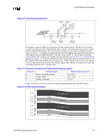
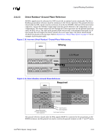
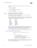
Layout/Routing Guidelines Figure 2-9. RSL Routing Dimensions RIMM_0 RIMM_1 MCH 0"-3.50" A 0.4"-0.45" B MCH to RIMM to First RIMM RIMM 0"-3" C RIMM to Termination To maintain a nominal 28 Ω trace impedance, the RSL signals must be 18 mils wide. To control crosstalk and odd/even mode velocity deltas, there must be a 10 mil ground isolation trace routed between adjacent RSL signals. The 10 mil ground isolation traces must be connected to ground with a via every 1". A 6 mil gap is required between the RSL signals and the ground isolation trace. These signals must be length matched to ±10 mils in line section "A" and ±2 mils in both line sections labeled "B" using the trace length matching methods in Section 2.6.2.6, "Length Matching Methods" on page 2-21. To ensure uniform trace lines, trace width variation must be uniform on all RSL signals at every neck-down for each line section. All RSL signals must have the same number of vias. It may be necessary to place vias on RSL signals where they are not necessary to meet this via loading requirement (i.e., dummy vias). Table 2-2. Placement Guidelines for Motherboard Routing Lengths Reference Trace Description Maximum Trace Length (in.) A MCH to first RIMM Connector B RIMM to RIMM C RIMM to Termination 0" to 3.50" 0.4" - 0.45" 0" to 3" Figure 2-10 shows a top view of the trace width/spacing requirements for the RSL signals. Figure 2-10. RSL Routing Diagram 18 mils 6 mils 10 mils 6 mils 18 mils 6 mils 10 mils 6 mils Space Space Space Space RSL Signal Trace Ground RSL Signal Trace Ground Intel®820 Chipset Design Guide 2-9
-
 1
1 -
2
-
3
-
4
-
5
-
6
-
7
-
8
-
9
-
10
-
11
-
12
-
13
-
14
-
15
-
16
-
17
-
18
-
19
-
20
-
21
-
22
-
23
-
24
-
25
-
26
-
27
-
28
-
29
-
 30
30 -
 31
31 -
 32
32 -
 33
33 -
 34
34 -
 35
35 -
 36
36 -
 37
37 -
 38
38 -
 39
39 -
 40
40 -
41
-
42
-
43
-
44
-
45
-
46
-
47
-
48
-
49
-
50
-
51
-
52
-
53
-
54
-
55
-
56
-
57
-
58
-
59
-
60
-
61
-
62
-
63
-
64
-
65
-
66
-
67
-
68
-
69
-
70
-
71
-
72
-
73
-
74
-
75
-
76
-
77
-
78
-
79
-
80
-
81
-
82
-
83
-
84
-
85
-
86
-
87
-
88
-
89
-
90
-
91
-
92
-
93
-
94
-
95
-
96
-
97
-
98
-
99
-
100
-
101
-
102
-
103
-
104
-
105
-
106
-
107
-
108
-
109
-
110
-
111
-
112
-
113
-
114
-
115
-
116
-
117
-
118
-
119
-
120
-
121
-
122
-
123
-
124
-
125
-
126
-
127
-
128
-
129
-
130
-
131
-
132
-
133
-
134
-
135
-
136
-
137
-
138
-
139
-
140
-
141
-
142
-
143
-
144
-
145
-
146
-
147
-
148
-
149
-
150
-
151
-
152
-
153
-
154
-
155
-
156
-
157
-
158
-
159
-
160
-
161
-
162
-
163
-
164
-
165
-
166
-
167
-
168
-
169
-
170
-
171
-
172
-
173
-
174
-
175
-
176
-
177
-
178
-
179
-
180
-
181
-
182
-
183
-
184
-
185
-
186
-
187
-
188
-
189
-
190
-
191
-
192
-
193
-
194
-
195
-
196
-
197
-
198
-
199
-
200
-
201
-
202
-
203
-
204
-
205
-
206
-
207
-
208
-
209
-
210
-
211
-
212
-
213
-
214
-
215
-
216
-
217
-
218
-
219
-
220
-
221
-
222
-
223
-
224
-
225
-
226
-
227
-
228
-
229
-
230
-
231
-
232
-
233
-
234
-
235
-
236
-
237
-
238
-
239
-
240
-
241
-
242
 |
 |
