Netgear GS716Tv2 GS716Tv2/GS724Tv3 Software Admin Manual - Page 200
Clear, Refresh, Cancel, Apply, Table, 7. FLASH Log Configuration Fields, 8. FLASH Log Fields
 |
View all Netgear GS716Tv2 manuals
Add to My Manuals
Save this manual to your list of manuals |
Page 200 highlights
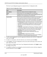
GS716Tv2 and GS724Tv3 Software Administration Manual Table 6-7. FLASH Log Configuration Fields Field Description Admin Status Severity Filter Enable or disable logging by selecting the corresponding check box. The default is Disable. • Enable: A log that is 'Enabled' logs messages. • Disable: A log that is 'Disabled' does not log messages. A log records messages equal to or above a configured severity threshold. Use the menu to select the severity of the logs. For example, if you select Error, the logged messages include Error, Critical, Alert, and Emergency. The default severity level is Alert(1). The severity can be one of the following levels: • Emergency (0): The highest level warning level. If the device is down or not functioning properly, an emergency log is saved to the device. • Alert (1): The second highest warning level. An alert log is saved if there is a serious device malfunction, such as all device features being down. Action must be taken immediately. • Critical (2): The third highest warning level. A critical log is saved if a critical device malfunction occurs, for example, two device ports are not functioning, while the rest of the device ports remain functional. • Error (3): A device error has occurred, such as if a port is offline. • Warning (4): The lowest level of a device warning. • Notice (5): Normal but significant conditions. Provides the network administrators with device information. • Info (6): Provides device information. • Debug (7): Provides detailed information about the log. Debugging should only be entered by qualified support personnel. The rest of the page displays the persistent log messages. Table 6-8. FLASH Log Fields Field Description Number of FLASH Messages Shows the number of persistent messages the system has logged. 2. Click Clear to clear the messages out of the buffered log. 3. Click Refresh to refresh the page with the most current data from the switch. 4. Click Cancel to cancel the configuration on the screen and reset the data on the screen to the latest value of the switch. 5. If you make any changes to the page, click Apply to apply the change to the system. 6-18 v1.0, July 2009 Monitoring the System
-
 1
1 -
2
-
3
-
4
-
5
-
6
-
7
-
8
-
9
-
10
-
11
-
12
-
13
-
14
-
15
-
16
-
17
-
18
-
19
-
20
-
21
-
22
-
23
-
24
-
25
-
26
-
27
-
28
-
29
-
30
-
31
-
32
-
33
-
34
-
35
-
36
-
37
-
38
-
39
-
40
-
41
-
42
-
43
-
44
-
45
-
46
-
47
-
48
-
49
-
50
-
51
-
52
-
53
-
54
-
55
-
56
-
57
-
58
-
59
-
60
-
61
-
62
-
63
-
64
-
65
-
66
-
67
-
68
-
69
-
70
-
71
-
72
-
73
-
74
-
75
-
76
-
77
-
78
-
79
-
80
-
81
-
82
-
83
-
84
-
85
-
86
-
87
-
88
-
89
-
90
-
91
-
92
-
93
-
94
-
95
-
96
-
97
-
98
-
99
-
100
-
101
-
102
-
103
-
104
-
105
-
106
-
107
-
108
-
109
-
110
-
111
-
112
-
113
-
114
-
115
-
116
-
117
-
118
-
119
-
120
-
121
-
122
-
123
-
124
-
125
-
126
-
127
-
128
-
129
-
130
-
131
-
132
-
133
-
134
-
135
-
136
-
137
-
138
-
139
-
140
-
141
-
142
-
143
-
144
-
145
-
146
-
147
-
148
-
149
-
150
-
151
-
152
-
153
-
154
-
155
-
156
-
157
-
158
-
159
-
160
-
161
-
162
-
163
-
164
-
165
-
166
-
167
-
168
-
169
-
170
-
171
-
172
-
173
-
174
-
175
-
176
-
177
-
178
-
179
-
180
-
181
-
182
-
183
-
184
-
185
-
186
-
187
-
188
-
189
-
190
-
191
-
192
-
193
-
194
-
 195
195 -
 196
196 -
 197
197 -
 198
198 -
 199
199 -
 200
200 -
 201
201 -
 202
202 -
 203
203 -
 204
204 -
 205
205 -
206
-
207
-
208
-
209
-
210
-
211
-
212
-
213
-
214
-
215
-
216
-
217
-
218
-
219
-
220
-
221
-
222
-
223
-
224
-
225
-
226
-
227
-
228
-
229
-
230
-
231
-
232
-
233
-
234
-
235
-
236
-
237
-
238
-
239
-
240
-
241
-
242
-
243
-
244
-
245
-
246
 |
 |
