Netgear GS716Tv2 GS716Tv2/GS724Tv3 Software Admin Manual - Page 241
CST Configuration on, VLAN ID: 300
 |
View all Netgear GS716Tv2 manuals
Add to My Manuals
Save this manual to your list of manuals |
Page 241 highlights
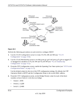
GS716Tv2 and GS724Tv3 Software Administration Manual Note: Bridge priority values are multiples of 4096. If you do not specify a root bridge and all switches have the same Bridge Priority value, the switch with the lowest MAC address is elected as the root bridge (see "CST Configuration" on page 3-19). 5. From the CST Port Configuration screen, select ports g1-g10 and g15-g24 and select Enable from the STP Status menu (see "CST Port Configuration" on page 3-21). 6. Click Apply. 7. Select ports g1-g5 (edge ports), and select Enable from the Fast Link menu. Since the edge ports are not at risk for network loops, ports with Fast Link enabled transition directly to the Forwarding state. 8. Click Apply. You can use the CST Port Status screen to view spanning tree information about each port. 9. From the MST Configuration screen, create a MST instances with the following settings: • MST ID: 1 • Priority: Use the default (32768) • VLAN ID: 300 For more information, see "MST Configuration" on page 3-26. 10. Click Add. 11. Create a second MST instance with the following settings • MST ID: 2 • Priority: 49152 • VLAN ID: 500 12. Click Add. In this example, assume that Switch 1 has become the Root bridge for the MST instance 1, and Switch 2 has become the Root bridge for MST instance 2. Switch 3 has hosts in the Sales department (ports g1, g2 and g3) and in the HR department (ports g4 and g5). Switches 1 and 2 Configuration Examples v1.0, July 2009 B-15
-
 1
1 -
2
-
3
-
4
-
5
-
6
-
7
-
8
-
9
-
10
-
11
-
12
-
13
-
14
-
15
-
16
-
17
-
18
-
19
-
20
-
21
-
22
-
23
-
24
-
25
-
26
-
27
-
28
-
29
-
30
-
31
-
32
-
33
-
34
-
35
-
36
-
37
-
38
-
39
-
40
-
41
-
42
-
43
-
44
-
45
-
46
-
47
-
48
-
49
-
50
-
51
-
52
-
53
-
54
-
55
-
56
-
57
-
58
-
59
-
60
-
61
-
62
-
63
-
64
-
65
-
66
-
67
-
68
-
69
-
70
-
71
-
72
-
73
-
74
-
75
-
76
-
77
-
78
-
79
-
80
-
81
-
82
-
83
-
84
-
85
-
86
-
87
-
88
-
89
-
90
-
91
-
92
-
93
-
94
-
95
-
96
-
97
-
98
-
99
-
100
-
101
-
102
-
103
-
104
-
105
-
106
-
107
-
108
-
109
-
110
-
111
-
112
-
113
-
114
-
115
-
116
-
117
-
118
-
119
-
120
-
121
-
122
-
123
-
124
-
125
-
126
-
127
-
128
-
129
-
130
-
131
-
132
-
133
-
134
-
135
-
136
-
137
-
138
-
139
-
140
-
141
-
142
-
143
-
144
-
145
-
146
-
147
-
148
-
149
-
150
-
151
-
152
-
153
-
154
-
155
-
156
-
157
-
158
-
159
-
160
-
161
-
162
-
163
-
164
-
165
-
166
-
167
-
168
-
169
-
170
-
171
-
172
-
173
-
174
-
175
-
176
-
177
-
178
-
179
-
180
-
181
-
182
-
183
-
184
-
185
-
186
-
187
-
188
-
189
-
190
-
191
-
192
-
193
-
194
-
195
-
196
-
197
-
198
-
199
-
200
-
201
-
202
-
203
-
204
-
205
-
206
-
207
-
208
-
209
-
210
-
211
-
212
-
213
-
214
-
215
-
216
-
217
-
218
-
219
-
220
-
221
-
222
-
223
-
224
-
225
-
226
-
227
-
228
-
229
-
230
-
231
-
232
-
233
-
234
-
235
-
 236
236 -
 237
237 -
 238
238 -
 239
239 -
 240
240 -
 241
241 -
 242
242 -
 243
243 -
 244
244 -
 245
245 -
 246
246
 |
 |
