Netgear GS716Tv2 GS716Tv2/GS724Tv3 Software Admin Manual - Page 233
From the IP ACL screen, create a new IP ACL with an IP ACL ID of 1 See, IP ACL on, IP Rules
 |
View all Netgear GS716Tv2 manuals
Add to My Manuals
Save this manual to your list of manuals |
Page 233 highlights
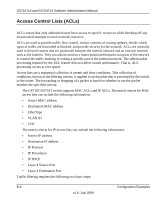
GS716Tv2 and GS724Tv3 Software Administration Manual 1. From the IP ACL screen, create a new IP ACL with an IP ACL ID of 1 (See "IP ACL" on page 5-47). 2. From the IP Rules screen, create a rule for IP ACL 1 with the following settings: • Rule ID: 1 • Action: Deny • Assign Queue ID: 0 (optional - 0 is the default value) • Match Every: False • Source IP Address: 192.168.187.0 • Source IP Mask: 255.255.255.0 For more information about IP ACL rules, see "IP Rules" on page 5-48. 3. Click Add. 4. From the IP Rules screen, create a rule for IP ACL 2 with the following settings: • Rule ID: 2 • Action: Permit • Match Every: True 5. Click Add. 6. From the IP Binding Configuration page, assign ACL ID 1 to the interface gigabit ports 14, 15, 16, 17, 18, 19, and 20, and assign a sequence number of 1 (See "IP Binding Configuration" on page 5-54). By default, this IP ACL is bound on the inbound direction, so it examines traffic as it enters the switch. 7. Click Apply. 8. From the IP Binding Configuration page, assign ACL ID 2 to the interface gigabit ports 14, 15, 16, 17, 18, 19, and 20, and assign a sequence number of 2. 9. Click Apply. 10. Use the IP Binding Table screen to view the interfaces and IP ACL binding information (See "IP Binding Table" on page 5-56). Configuration Examples B-7 v1.0, July 2009
-
 1
1 -
2
-
3
-
4
-
5
-
6
-
7
-
8
-
9
-
10
-
11
-
12
-
13
-
14
-
15
-
16
-
17
-
18
-
19
-
20
-
21
-
22
-
23
-
24
-
25
-
26
-
27
-
28
-
29
-
30
-
31
-
32
-
33
-
34
-
35
-
36
-
37
-
38
-
39
-
40
-
41
-
42
-
43
-
44
-
45
-
46
-
47
-
48
-
49
-
50
-
51
-
52
-
53
-
54
-
55
-
56
-
57
-
58
-
59
-
60
-
61
-
62
-
63
-
64
-
65
-
66
-
67
-
68
-
69
-
70
-
71
-
72
-
73
-
74
-
75
-
76
-
77
-
78
-
79
-
80
-
81
-
82
-
83
-
84
-
85
-
86
-
87
-
88
-
89
-
90
-
91
-
92
-
93
-
94
-
95
-
96
-
97
-
98
-
99
-
100
-
101
-
102
-
103
-
104
-
105
-
106
-
107
-
108
-
109
-
110
-
111
-
112
-
113
-
114
-
115
-
116
-
117
-
118
-
119
-
120
-
121
-
122
-
123
-
124
-
125
-
126
-
127
-
128
-
129
-
130
-
131
-
132
-
133
-
134
-
135
-
136
-
137
-
138
-
139
-
140
-
141
-
142
-
143
-
144
-
145
-
146
-
147
-
148
-
149
-
150
-
151
-
152
-
153
-
154
-
155
-
156
-
157
-
158
-
159
-
160
-
161
-
162
-
163
-
164
-
165
-
166
-
167
-
168
-
169
-
170
-
171
-
172
-
173
-
174
-
175
-
176
-
177
-
178
-
179
-
180
-
181
-
182
-
183
-
184
-
185
-
186
-
187
-
188
-
189
-
190
-
191
-
192
-
193
-
194
-
195
-
196
-
197
-
198
-
199
-
200
-
201
-
202
-
203
-
204
-
205
-
206
-
207
-
208
-
209
-
210
-
211
-
212
-
213
-
214
-
215
-
216
-
217
-
218
-
219
-
220
-
221
-
222
-
223
-
224
-
225
-
226
-
227
-
 228
228 -
 229
229 -
 230
230 -
 231
231 -
 232
232 -
 233
233 -
 234
234 -
 235
235 -
 236
236 -
 237
237 -
 238
238 -
239
-
240
-
241
-
242
-
243
-
244
-
245
-
246
 |
 |
