Netgear GS716Tv2 GS716Tv2/GS724Tv3 Software Admin Manual - Page 90
MST Configuration, Switching, Advanced
 |
View all Netgear GS716Tv2 manuals
Add to My Manuals
Save this manual to your list of manuals |
Page 90 highlights
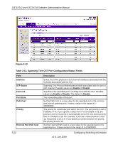
GS716Tv2 and GS724Tv3 Software Administration Manual MST Configuration Use the Spanning Tree MST Configuration page to configure Multiple Spanning Tree (MST) on the switch. To display the Spanning Tree MST Configuration page: 1. Click SwitchingSTPAdvanced MST Configuration in the navigation tree. Use this page to create and configure a new MST or select an existing MST to display or configure. Figure 3-16 Table 3-16. Spanning Tree MST Configuration Field MST ID Priority Description This is only visible when the select option of the MST ID select box is selected. The ID of the MST being created. Valid values for this are between 1 and 4094. Specifies the bridge priority value for the MST. When switches or bridges are running STP, each is assigned a priority. After exchanging BPDUs, the switch with the lowest priority value becomes the root bridge. The bridge priority is a multiple of 4096. If you specify a priority that is not a multiple of 4096, the priority is automatically set to the next lowest priority that is a multiple of 4096. For example, if the priority is attempted to be set to any value between 0 and 4095, it will be set to 0. The default priority is 32768.The valid range is 0-61440. 3-26 v1.0, July 2009 Configuring Switching Information
-
 1
1 -
2
-
3
-
4
-
5
-
6
-
7
-
8
-
9
-
10
-
11
-
12
-
13
-
14
-
15
-
16
-
17
-
18
-
19
-
20
-
21
-
22
-
23
-
24
-
25
-
26
-
27
-
28
-
29
-
30
-
31
-
32
-
33
-
34
-
35
-
36
-
37
-
38
-
39
-
40
-
41
-
42
-
43
-
44
-
45
-
46
-
47
-
48
-
49
-
50
-
51
-
52
-
53
-
54
-
55
-
56
-
57
-
58
-
59
-
60
-
61
-
62
-
63
-
64
-
65
-
66
-
67
-
68
-
69
-
70
-
71
-
72
-
73
-
74
-
75
-
76
-
77
-
78
-
79
-
80
-
81
-
82
-
83
-
84
-
 85
85 -
 86
86 -
 87
87 -
 88
88 -
 89
89 -
 90
90 -
 91
91 -
 92
92 -
 93
93 -
 94
94 -
 95
95 -
96
-
97
-
98
-
99
-
100
-
101
-
102
-
103
-
104
-
105
-
106
-
107
-
108
-
109
-
110
-
111
-
112
-
113
-
114
-
115
-
116
-
117
-
118
-
119
-
120
-
121
-
122
-
123
-
124
-
125
-
126
-
127
-
128
-
129
-
130
-
131
-
132
-
133
-
134
-
135
-
136
-
137
-
138
-
139
-
140
-
141
-
142
-
143
-
144
-
145
-
146
-
147
-
148
-
149
-
150
-
151
-
152
-
153
-
154
-
155
-
156
-
157
-
158
-
159
-
160
-
161
-
162
-
163
-
164
-
165
-
166
-
167
-
168
-
169
-
170
-
171
-
172
-
173
-
174
-
175
-
176
-
177
-
178
-
179
-
180
-
181
-
182
-
183
-
184
-
185
-
186
-
187
-
188
-
189
-
190
-
191
-
192
-
193
-
194
-
195
-
196
-
197
-
198
-
199
-
200
-
201
-
202
-
203
-
204
-
205
-
206
-
207
-
208
-
209
-
210
-
211
-
212
-
213
-
214
-
215
-
216
-
217
-
218
-
219
-
220
-
221
-
222
-
223
-
224
-
225
-
226
-
227
-
228
-
229
-
230
-
231
-
232
-
233
-
234
-
235
-
236
-
237
-
238
-
239
-
240
-
241
-
242
-
243
-
244
-
245
-
246
 |
 |
