Netgear GS716Tv2 GS716Tv2/GS724Tv3 Software Admin Manual - Page 67
Cancel, Apply, Table, 1. Port Configuration Fields continued
 |
View all Netgear GS716Tv2 manuals
Add to My Manuals
Save this manual to your list of manuals |
Page 67 highlights
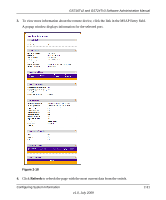
GS716Tv2 and GS724Tv3 Software Administration Manual Table 3-1. Port Configuration Fields (continued) Field Auto Power Down Mode Short Cable Mode Physical Status Link Status Link Trap Maximum Frame Size MAC Address PortList Bit Offset ifIndex Description Use the menu to select the port's Green Ethernet mode, which can be one of the following: Enable: Specifies that when the port link is down, the PHY automatically goes down for a short amount of time, and wakes up to check link pulses, performs auto-negotiation and saving power consumption routines when a link partner is unavailable. • Disable: The port is administratively down and does not participate in Green Ethernet mode. Use the menu to select the port's Green Ethernet mode, which can be one of the following: • Enable: Specifies that cable test is performed when the port link is up at 1 Gbps and if the cable is less than 10m, PHYs are placed in low power mode (nominal power). • Disable: The port is administratively down and does not participate in Green Ethernet mode. Indicates the physical port's speed and duplex mode Indicates whether the Link is up or down. This object determines whether or not to send a trap when link status changes. The factory default is enabled: • Enable: Specifies that the system sends a trap when the link status changes. • Disable: Specifies that the system does not send a trap when the link status changes. Indicates the maximum Ethernet frame size the interface supports or is configured to support. The frame size includes the Ethernet header, CRC, and payload. (1518-9216). The default maximum frame size is 1518. Displays the physical address of the specified interface. Display the bit offset value which corresponds to the port when the MIB object type PortList is used to manage in SNMP. The ifIndex of the interface table entry associated with this port. If the interface field is set to All, this field is blank. 2. Click Cancel to cancel the configuration on the screen and reset the data on the screen to the latest value of the switch. 3. If you make any changes to the page, click Apply to apply the changes to the system. Configuring Switching Information 3-3 v1.0, July 2009
-
 1
1 -
2
-
3
-
4
-
5
-
6
-
7
-
8
-
9
-
10
-
11
-
12
-
13
-
14
-
15
-
16
-
17
-
18
-
19
-
20
-
21
-
22
-
23
-
24
-
25
-
26
-
27
-
28
-
29
-
30
-
31
-
32
-
33
-
34
-
35
-
36
-
37
-
38
-
39
-
40
-
41
-
42
-
43
-
44
-
45
-
46
-
47
-
48
-
49
-
50
-
51
-
52
-
53
-
54
-
55
-
56
-
57
-
58
-
59
-
60
-
61
-
 62
62 -
 63
63 -
 64
64 -
 65
65 -
 66
66 -
 67
67 -
 68
68 -
 69
69 -
 70
70 -
 71
71 -
 72
72 -
73
-
74
-
75
-
76
-
77
-
78
-
79
-
80
-
81
-
82
-
83
-
84
-
85
-
86
-
87
-
88
-
89
-
90
-
91
-
92
-
93
-
94
-
95
-
96
-
97
-
98
-
99
-
100
-
101
-
102
-
103
-
104
-
105
-
106
-
107
-
108
-
109
-
110
-
111
-
112
-
113
-
114
-
115
-
116
-
117
-
118
-
119
-
120
-
121
-
122
-
123
-
124
-
125
-
126
-
127
-
128
-
129
-
130
-
131
-
132
-
133
-
134
-
135
-
136
-
137
-
138
-
139
-
140
-
141
-
142
-
143
-
144
-
145
-
146
-
147
-
148
-
149
-
150
-
151
-
152
-
153
-
154
-
155
-
156
-
157
-
158
-
159
-
160
-
161
-
162
-
163
-
164
-
165
-
166
-
167
-
168
-
169
-
170
-
171
-
172
-
173
-
174
-
175
-
176
-
177
-
178
-
179
-
180
-
181
-
182
-
183
-
184
-
185
-
186
-
187
-
188
-
189
-
190
-
191
-
192
-
193
-
194
-
195
-
196
-
197
-
198
-
199
-
200
-
201
-
202
-
203
-
204
-
205
-
206
-
207
-
208
-
209
-
210
-
211
-
212
-
213
-
214
-
215
-
216
-
217
-
218
-
219
-
220
-
221
-
222
-
223
-
224
-
225
-
226
-
227
-
228
-
229
-
230
-
231
-
232
-
233
-
234
-
235
-
236
-
237
-
238
-
239
-
240
-
241
-
242
-
243
-
244
-
245
-
246
 |
 |
