Netgear GS716Tv2 GS716Tv2/GS724Tv3 Software Admin Manual - Page 229
VLAN Configuration on In the Basic VLAN Configuration screen see
 |
View all Netgear GS716Tv2 manuals
Add to My Manuals
Save this manual to your list of manuals |
Page 229 highlights
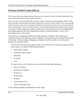
GS716Tv2 and GS724Tv3 Software Administration Manual In this example, you create two new VLANs, change the port membership for default VLAN 1, and assign port members to the two new VLANs: 1. In the Basic VLAN Configuration screen (see "VLAN Configuration" on page 3-10), create the following VLANs: • A VLAN with VLAN ID 10. • A VLAN with VLAN ID 20. 2. In the VLAN Membership screen (see "VLAN Membership Configuration" on page 3-12) specify the VLAN membership as follows: • For the default VLAN with VLAN ID 1, specify the following members: port 7 (U) and port 8 (U). • For the VLAN with VLAN ID 10, specify the following members: port 1 (U), port 2 (U), and port 3 (T). • For the VLAN with VLAN ID 20, specify the following members: port 4 (U), port 5 (T), and port 6 (U). 3. In the Port PVID Configuration screen (see "Port VLAN ID Configuration" on page 3-14), specify the PVID for ports g1 and g4 so that packets entering these ports are tagged with the port VLAN ID: • Port g1: PVID 10 • Port g4: PVID 20 4. With the VLAN configuration that you set up, the following situations produce results as described: • If an untagged packet enters port 1, the switch tags it with VLAN ID 10. The packet has access to port 2 and port 3. The outgoing packet is stripped of its tag to leave port 2 as an untagged packet. For port 3, the outgoing packet leaves as a tagged packet with VLAN ID 10. • If a tagged packet with VLAN ID 10 enters port 3, the packet has access to port 1 and port 2. If the packet leaves port 1 or port 2, it is stripped of its tag to leave the switch as an untagged packet. • If an untagged packet enters port 4, the switch tags it with VLAN ID 20. The packet has access to port 5 and port 6. The outgoing packet is stripped of its tag to become an untagged packet as it leaves port 6. For port 5, the outgoing packet leaves as a tagged packet with VLAN ID 20. Configuration Examples B-3 v1.0, July 2009
-
 1
1 -
2
-
3
-
4
-
5
-
6
-
7
-
8
-
9
-
10
-
11
-
12
-
13
-
14
-
15
-
16
-
17
-
18
-
19
-
20
-
21
-
22
-
23
-
24
-
25
-
26
-
27
-
28
-
29
-
30
-
31
-
32
-
33
-
34
-
35
-
36
-
37
-
38
-
39
-
40
-
41
-
42
-
43
-
44
-
45
-
46
-
47
-
48
-
49
-
50
-
51
-
52
-
53
-
54
-
55
-
56
-
57
-
58
-
59
-
60
-
61
-
62
-
63
-
64
-
65
-
66
-
67
-
68
-
69
-
70
-
71
-
72
-
73
-
74
-
75
-
76
-
77
-
78
-
79
-
80
-
81
-
82
-
83
-
84
-
85
-
86
-
87
-
88
-
89
-
90
-
91
-
92
-
93
-
94
-
95
-
96
-
97
-
98
-
99
-
100
-
101
-
102
-
103
-
104
-
105
-
106
-
107
-
108
-
109
-
110
-
111
-
112
-
113
-
114
-
115
-
116
-
117
-
118
-
119
-
120
-
121
-
122
-
123
-
124
-
125
-
126
-
127
-
128
-
129
-
130
-
131
-
132
-
133
-
134
-
135
-
136
-
137
-
138
-
139
-
140
-
141
-
142
-
143
-
144
-
145
-
146
-
147
-
148
-
149
-
150
-
151
-
152
-
153
-
154
-
155
-
156
-
157
-
158
-
159
-
160
-
161
-
162
-
163
-
164
-
165
-
166
-
167
-
168
-
169
-
170
-
171
-
172
-
173
-
174
-
175
-
176
-
177
-
178
-
179
-
180
-
181
-
182
-
183
-
184
-
185
-
186
-
187
-
188
-
189
-
190
-
191
-
192
-
193
-
194
-
195
-
196
-
197
-
198
-
199
-
200
-
201
-
202
-
203
-
204
-
205
-
206
-
207
-
208
-
209
-
210
-
211
-
212
-
213
-
214
-
215
-
216
-
217
-
218
-
219
-
220
-
221
-
222
-
223
-
 224
224 -
 225
225 -
 226
226 -
 227
227 -
 228
228 -
 229
229 -
 230
230 -
 231
231 -
 232
232 -
 233
233 -
 234
234 -
235
-
236
-
237
-
238
-
239
-
240
-
241
-
242
-
243
-
244
-
245
-
246
 |
 |
