Netgear GS716Tv2 GS716Tv2/GS724Tv3 Software Admin Manual - Page 239
MSTP Example Configuration, Region traverses only MST bridges and LANs in that region
 |
View all Netgear GS716Tv2 manuals
Add to My Manuals
Save this manual to your list of manuals |
Page 239 highlights
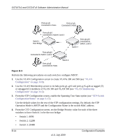
GS716Tv2 and GS724Tv3 Software Administration Manual To support multiple spanning trees, a MSTP bridge has to be configured with an unambiguous assignment of VLAN IDs (VIDs) to spanning trees. This is achieved by: 1. Ensuring that the allocation of VIDs to FIDs is unambiguous. 2. Ensuring that each FID supported by the Bridge is allocated to exactly one Spanning Tree Instance. The combination of VID to FID and then FID to MSTI allocation defines a mapping of VIDs to spanning tree instances, represented by the MST Configuration Table. With this allocation we ensure that every VLAN is assigned to one and only one MSTI. The CIST is also an instance of spanning tree with a MSTID of 0. An instance may occur that has no VIDs allocated to it, but every VLAN must be allocated to one of the other instances of spanning tree. The portion of the active topology of the network that connects any two bridges in the same MST Region traverses only MST bridges and LANs in that region, and never Bridges of any kind outside the Region, in other words connectivity within the region is independent of external connectivity. MSTP Example Configuration This example shows how to create an MSTP instance from the GS716T/GS724T switch. The example network has three different GS716T/GS724T switches that serve different locations in the network. In this example, ports g1-g5 are connected to host stations, so those links are not subject to network loops. Ports g6-g10 are connected across switches 1, 2 and 3. Configuration Examples v1.0, July 2009 B-13
-
 1
1 -
2
-
3
-
4
-
5
-
6
-
7
-
8
-
9
-
10
-
11
-
12
-
13
-
14
-
15
-
16
-
17
-
18
-
19
-
20
-
21
-
22
-
23
-
24
-
25
-
26
-
27
-
28
-
29
-
30
-
31
-
32
-
33
-
34
-
35
-
36
-
37
-
38
-
39
-
40
-
41
-
42
-
43
-
44
-
45
-
46
-
47
-
48
-
49
-
50
-
51
-
52
-
53
-
54
-
55
-
56
-
57
-
58
-
59
-
60
-
61
-
62
-
63
-
64
-
65
-
66
-
67
-
68
-
69
-
70
-
71
-
72
-
73
-
74
-
75
-
76
-
77
-
78
-
79
-
80
-
81
-
82
-
83
-
84
-
85
-
86
-
87
-
88
-
89
-
90
-
91
-
92
-
93
-
94
-
95
-
96
-
97
-
98
-
99
-
100
-
101
-
102
-
103
-
104
-
105
-
106
-
107
-
108
-
109
-
110
-
111
-
112
-
113
-
114
-
115
-
116
-
117
-
118
-
119
-
120
-
121
-
122
-
123
-
124
-
125
-
126
-
127
-
128
-
129
-
130
-
131
-
132
-
133
-
134
-
135
-
136
-
137
-
138
-
139
-
140
-
141
-
142
-
143
-
144
-
145
-
146
-
147
-
148
-
149
-
150
-
151
-
152
-
153
-
154
-
155
-
156
-
157
-
158
-
159
-
160
-
161
-
162
-
163
-
164
-
165
-
166
-
167
-
168
-
169
-
170
-
171
-
172
-
173
-
174
-
175
-
176
-
177
-
178
-
179
-
180
-
181
-
182
-
183
-
184
-
185
-
186
-
187
-
188
-
189
-
190
-
191
-
192
-
193
-
194
-
195
-
196
-
197
-
198
-
199
-
200
-
201
-
202
-
203
-
204
-
205
-
206
-
207
-
208
-
209
-
210
-
211
-
212
-
213
-
214
-
215
-
216
-
217
-
218
-
219
-
220
-
221
-
222
-
223
-
224
-
225
-
226
-
227
-
228
-
229
-
230
-
231
-
232
-
233
-
 234
234 -
 235
235 -
 236
236 -
 237
237 -
 238
238 -
 239
239 -
 240
240 -
 241
241 -
 242
242 -
 243
243 -
 244
244 -
245
-
246
 |
 |
