HP rp3440 User Service Guide, Sixth Edition - HP 9000 rp3410/rp3440 - Page 100
Installing Your A6150B Graphics Card, Connecting a Monitor Using the VGA Port
 |
View all HP rp3440 manuals
Add to My Manuals
Save this manual to your list of manuals |
Page 100 highlights
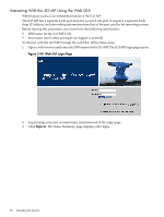
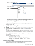
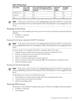
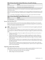
Installing Your A6150B Graphics Card If you ordered the A6150B graphics card kit for installation into a HP 9000 rp3410 or rp3440 server, install the graphics card to activate graphics capability. Do not install the USB card; it is not supported. USB capability is already incorporated into the rp3410 or rp3440 server, and the USB ports are located on the rear panel. To install the A6150 graphics card, see "Replacing a PCI or Graphics Card" (page 170). Connecting a Monitor Using the VGA Port Use these procedures to connect a monitor to the VGA port on the rear of the server. NOTE: You cannot access the iLO MP using VGA. This method requires three elements: • Monitor (with a VGA connector) • Keyboard (with a USB connector) • Mouse (with a USB connector) IMPORTANT: The server console output does not display on the console device screen until the server boots to the BCH Main Menu. Start a console session using the RS-232 serial port method to view console output before booting to the BCH Main Menu or to access the iLO MP. To access the graphic console with VGA, follow these steps: 1. Remove the VGA port cover on the rear of the server. 2. Connect the monitor, keyboard, and mouse cables. a. Connect the monitor VGA cable to the appropriate VGA port on the server. b. Connect the keyboard USB cable to the appropriate USB port on the server. c. Connect the mouse USB cable to the appropriate USB port on the server. 3. Power on the server. The BCH Main Menu prompt displays. The graphic console output displays on the monitor screen. Powering the Server ON and OFF This section provides information and procedures for powering the server on and off. Power States The server has three power states: • Standby power • Full power • Off Plug the power cord into the appropriate receptacle on the rear of the server to achieve the standby power state; the front panel Power button is not turned on. Full power occurs when the power cord is plugged into the appropriate receptacle, and either the power is activated through the iLO MP PC command, or the Power button is activated. In the off state, the power cords are not plugged in. Table 3-8 lists the server power states. 100 Installing the System
-
 1
1 -
2
-
3
-
4
-
5
-
6
-
7
-
8
-
9
-
10
-
11
-
12
-
13
-
14
-
15
-
16
-
17
-
18
-
19
-
20
-
21
-
22
-
23
-
24
-
25
-
26
-
27
-
28
-
29
-
30
-
31
-
32
-
33
-
34
-
35
-
36
-
37
-
38
-
39
-
40
-
41
-
42
-
43
-
44
-
45
-
46
-
47
-
48
-
49
-
50
-
51
-
52
-
53
-
54
-
55
-
56
-
57
-
58
-
59
-
60
-
61
-
62
-
63
-
64
-
65
-
66
-
67
-
68
-
69
-
70
-
71
-
72
-
73
-
74
-
75
-
76
-
77
-
78
-
79
-
80
-
81
-
82
-
83
-
84
-
85
-
86
-
87
-
88
-
89
-
90
-
91
-
92
-
93
-
94
-
 95
95 -
 96
96 -
 97
97 -
 98
98 -
 99
99 -
 100
100 -
 101
101 -
 102
102 -
 103
103 -
 104
104 -
 105
105 -
106
-
107
-
108
-
109
-
110
-
111
-
112
-
113
-
114
-
115
-
116
-
117
-
118
-
119
-
120
-
121
-
122
-
123
-
124
-
125
-
126
-
127
-
128
-
129
-
130
-
131
-
132
-
133
-
134
-
135
-
136
-
137
-
138
-
139
-
140
-
141
-
142
-
143
-
144
-
145
-
146
-
147
-
148
-
149
-
150
-
151
-
152
-
153
-
154
-
155
-
156
-
157
-
158
-
159
-
160
-
161
-
162
-
163
-
164
-
165
-
166
-
167
-
168
-
169
-
170
-
171
-
172
-
173
-
174
-
175
-
176
-
177
-
178
-
179
-
180
-
181
-
182
-
183
-
184
-
185
-
186
-
187
-
188
-
189
-
190
-
191
-
192
-
193
-
194
-
195
-
196
-
197
-
198
-
199
-
200
-
201
-
202
-
203
-
204
-
205
-
206
-
207
-
208
-
209
-
210
 |
 |