HP rp3440 User Service Guide, Sixth Edition - HP 9000 rp3410/rp3440 - Page 87
HP Rack, Non-HP Rack, Pedestal Mount, Connecting the Cables, AC Input Power, Core I/O Connections - serial console
 |
View all HP rp3440 manuals
Add to My Manuals
Save this manual to your list of manuals |
Page 87 highlights
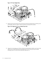
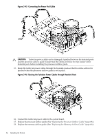
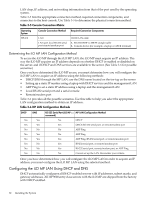
HP Rack HP 9000 entry class servers that are installed into racks are shipped with equipment mounting slides. The Mid-Weight Slide Kit, (HP part number 5065-7291) is provided with each set of slides. Follow the steps in the kit installation guide to determine where and how to place the server into the rack. The following are additional instructions for installing the server into the rack: 1. Switch the cable management arm (CMA) from a left- to a right-mount configuration. The CMA is factory-configured to mount on the left side of the server (as viewed from the rear of the chassis). Mount the CMA on the right side of the server to ensure easy removal of the power supplies. 2. Remove two T120 screws from the server bezel; one screw from the same location on each side of the server. The screws are located behind the pull handles. Non-HP Rack Use the Mounting in non-HP racks guide for evaluating the installation of HP equipment in non-HP racks. The guide provides information to help you determine if you need to qualify whether you can install, maintain, and service any HP equipment in a non-HP rack. The guide is located on the HP website at http://www.hp.com/racksolutions. Select Mounting information from the menu and select the guide titled Mounting in non-HP racks. Pedestal Mount If you ordered the server as rackless, it has a pedestal pre-installed at the factory. If the server is a rack-mounted and you want to change it to a pedestal-mount (rackless), you need a Server Rackless Mount Kit. This kit comes with an installation guide titled Converting Your Rack Server to a Rackless Mount (part number A6979-96001). To convert a rack-mount server to a pedestal-mount server, see Converting Your Rack Server to a Pedestal Server on the HP website at http://www.hp.com/. Follow the instructions in the kit installation guide to attach the pedestal to the server. Connecting the Cables This section describes the cables to connect to power the server and to provide LAN connectivity for the server. AC Input Power The server comes with one or two power supplies installed. A power supply includes an AC input connector which is rated for 200 to 240 VAC at 13 amps. If two power supplies are installed, both power supplies must be connected separately to an AC power source. Core I/O Connections Each HP 9000 rp3410 and rp3440 server core I/O includes: • Four USB ports • Two 9-pin serial ports (console A and serial B are for factory use only) • One iLO MP I/O interface - One 10/100 management LAN-RJ45 - One 25-pin serial, console/remote/UPS Connecting the Cables 87
-
 1
1 -
2
-
3
-
4
-
5
-
6
-
7
-
8
-
9
-
10
-
11
-
12
-
13
-
14
-
15
-
16
-
17
-
18
-
19
-
20
-
21
-
22
-
23
-
24
-
25
-
26
-
27
-
28
-
29
-
30
-
31
-
32
-
33
-
34
-
35
-
36
-
37
-
38
-
39
-
40
-
41
-
42
-
43
-
44
-
45
-
46
-
47
-
48
-
49
-
50
-
51
-
52
-
53
-
54
-
55
-
56
-
57
-
58
-
59
-
60
-
61
-
62
-
63
-
64
-
65
-
66
-
67
-
68
-
69
-
70
-
71
-
72
-
73
-
74
-
75
-
76
-
77
-
78
-
79
-
80
-
81
-
 82
82 -
 83
83 -
 84
84 -
 85
85 -
 86
86 -
 87
87 -
 88
88 -
 89
89 -
 90
90 -
 91
91 -
 92
92 -
93
-
94
-
95
-
96
-
97
-
98
-
99
-
100
-
101
-
102
-
103
-
104
-
105
-
106
-
107
-
108
-
109
-
110
-
111
-
112
-
113
-
114
-
115
-
116
-
117
-
118
-
119
-
120
-
121
-
122
-
123
-
124
-
125
-
126
-
127
-
128
-
129
-
130
-
131
-
132
-
133
-
134
-
135
-
136
-
137
-
138
-
139
-
140
-
141
-
142
-
143
-
144
-
145
-
146
-
147
-
148
-
149
-
150
-
151
-
152
-
153
-
154
-
155
-
156
-
157
-
158
-
159
-
160
-
161
-
162
-
163
-
164
-
165
-
166
-
167
-
168
-
169
-
170
-
171
-
172
-
173
-
174
-
175
-
176
-
177
-
178
-
179
-
180
-
181
-
182
-
183
-
184
-
185
-
186
-
187
-
188
-
189
-
190
-
191
-
192
-
193
-
194
-
195
-
196
-
197
-
198
-
199
-
200
-
201
-
202
-
203
-
204
-
205
-
206
-
207
-
208
-
209
-
210
 |
 |