HP rp3440 User Service Guide, Sixth Edition - HP 9000 rp3410/rp3440 - Page 152
Removing System Memory, WARNING, CAUTION
 |
View all HP rp3440 manuals
Add to My Manuals
Save this manual to your list of manuals |
Page 152 highlights
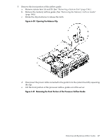
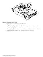
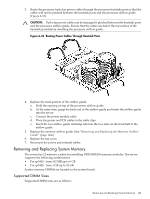
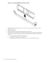
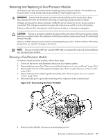
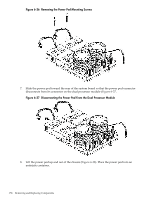
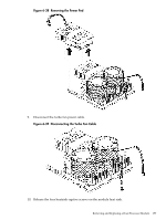
NOTE: When replacing deallocated memory ranks on a server with system firmware version 45.11 or greater, you must perform the following procedure before replacing the deallocated memory. This procedure is necessary to ensure that the memory is properly reallocated upon server boot. To ensure the repaired memory rank reallocates properly, follow these steps: 1. Boot to BCH. 2. Enter the in me command to view the deconfigured quad of memory. 3. Enter the ser pdt clear command. The following message displays followed by a 30 second delay: If DIMM replacement is necessary, power off the system now: Use ^B MP:CM> PC -OFF -NC, then pull power cord and replace DIMM. Otherwise, the system automatically reboots in 30 seconds. 4. You must remove power from the system within 30 seconds. 5. For instructions on removing and replacing the memory DIMM, see "Removing and Replacing System Memory" (page 149). Removing System Memory WARNING! Before removing or replacing system memory, ensure that the server is powered off and all the power sources have been disconnected from the server. Voltages are present at various locations within the server whenever an AC power source is connected. This voltage is present even when the main power switch is in the off position. Failure to observe this warning can result in personal injury or damage to equipment. CAUTION: Observe all ESD safety precautions before attempting this procedure. Failure to follow ESD safety precautions can result in damage to the server. To remove a DIMM, follow these steps: 1. Power off the server and disconnect the power and external cables. 2. Remove the top cover. (See "Removing and Replacing Server Covers and Bezel" (page 126).) 3. Remove the memory airflow guide. (See "Removing and Replacing the Memory Airflow Guide" (page 144).) 4. Identify the DIMM to be removed and push the appropriate extraction levers found on either side of the DIMM connector outward to the open position. The DIMM ejects from the connector. 5. Remove the DIMM from the socket. If the removed memory is functional, store it in a static-free container for future use. Installing System Memory Memory modules must be loaded in the correct order: • In the HP 9000 rp3410 server, the first four DIMMs must be installed as ordered pairs of equal size. The DIMM in socket 0A must match the DIMM in socket 0B. If a second pair is added (sockets 1A and 1B), the DIMMs must match the DIMMs in sockets 0A and 0B. Additional DIMMs (DIMM sockets 5 through 12) must be installed as quads (identical groups of four-two matched pairs). This requirement is summarized as: • 0A and 0B must be an identical pair • 1A and 1B must be identical to the pair in sockets 0A and 0B 152 Removing and Replacing Components
-
 1
1 -
2
-
3
-
4
-
5
-
6
-
7
-
8
-
9
-
10
-
11
-
12
-
13
-
14
-
15
-
16
-
17
-
18
-
19
-
20
-
21
-
22
-
23
-
24
-
25
-
26
-
27
-
28
-
29
-
30
-
31
-
32
-
33
-
34
-
35
-
36
-
37
-
38
-
39
-
40
-
41
-
42
-
43
-
44
-
45
-
46
-
47
-
48
-
49
-
50
-
51
-
52
-
53
-
54
-
55
-
56
-
57
-
58
-
59
-
60
-
61
-
62
-
63
-
64
-
65
-
66
-
67
-
68
-
69
-
70
-
71
-
72
-
73
-
74
-
75
-
76
-
77
-
78
-
79
-
80
-
81
-
82
-
83
-
84
-
85
-
86
-
87
-
88
-
89
-
90
-
91
-
92
-
93
-
94
-
95
-
96
-
97
-
98
-
99
-
100
-
101
-
102
-
103
-
104
-
105
-
106
-
107
-
108
-
109
-
110
-
111
-
112
-
113
-
114
-
115
-
116
-
117
-
118
-
119
-
120
-
121
-
122
-
123
-
124
-
125
-
126
-
127
-
128
-
129
-
130
-
131
-
132
-
133
-
134
-
135
-
136
-
137
-
138
-
139
-
140
-
141
-
142
-
143
-
144
-
145
-
146
-
 147
147 -
 148
148 -
 149
149 -
 150
150 -
 151
151 -
 152
152 -
 153
153 -
 154
154 -
 155
155 -
 156
156 -
 157
157 -
158
-
159
-
160
-
161
-
162
-
163
-
164
-
165
-
166
-
167
-
168
-
169
-
170
-
171
-
172
-
173
-
174
-
175
-
176
-
177
-
178
-
179
-
180
-
181
-
182
-
183
-
184
-
185
-
186
-
187
-
188
-
189
-
190
-
191
-
192
-
193
-
194
-
195
-
196
-
197
-
198
-
199
-
200
-
201
-
202
-
203
-
204
-
205
-
206
-
207
-
208
-
209
-
210
 |
 |