HP rp3440 User Service Guide, Sixth Edition - HP 9000 rp3410/rp3440 - Page 149
Removing and Replacing System Memory, Supported DIMM Sizes,
 |
View all HP rp3440 manuals
Add to My Manuals
Save this manual to your list of manuals |
Page 149 highlights
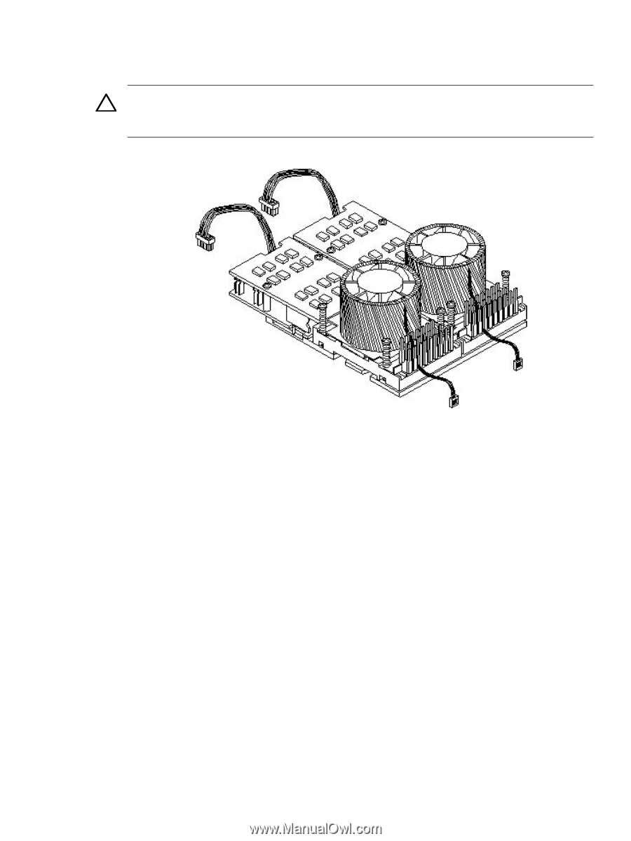
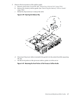
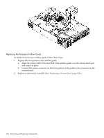
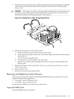
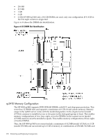
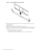
3. Route the processor turbo fan power cables through the processor heatsink posts so that the cables will not be pinched between the heatsink posts and the processor airflow guide (Figure 6-32). CAUTION: Turbo fan power cables can be damaged if pinched between the heatsink posts and the processor airflow guide. Ensure that the cables are below the top surface of the heatsink posts before installing the processor airflow guide. Figure 6-32 Routing Power Cables Through Heatsink Posts 4. Replace the main portion of the airflow guide: a. Hold the opening on top of the processor airflow guide. b. At the same time, grasp the back end of the airflow guide and insert the airflow guide into the server. c. Connect the power module cable. d. Place the power and IDE cables in the cable clips. e. Insert the two airflow guide retaining tabs into the two slots on the front half of the airflow guide. 5. Replace the memory airflow guide. (See "Removing and Replacing the Memory Airflow Guide" (page 144).) 6. Replace the top cover. 7. Reconnect the power and external cables. Removing and Replacing System Memory The server has 12 memory sockets for installing DDR SDRAM memory modules. The server supports the following combinations • For rp3410 - from 512 MB up to 6 GB • For rp3440 - from 1 GB up to 32 GB System memory DIMMs are located on the system board. Supported DIMM Sizes Supported DIMM sizes are as follows: Removing and Replacing System Memory 149
-
 1
1 -
2
-
3
-
4
-
5
-
6
-
7
-
8
-
9
-
10
-
11
-
12
-
13
-
14
-
15
-
16
-
17
-
18
-
19
-
20
-
21
-
22
-
23
-
24
-
25
-
26
-
27
-
28
-
29
-
30
-
31
-
32
-
33
-
34
-
35
-
36
-
37
-
38
-
39
-
40
-
41
-
42
-
43
-
44
-
45
-
46
-
47
-
48
-
49
-
50
-
51
-
52
-
53
-
54
-
55
-
56
-
57
-
58
-
59
-
60
-
61
-
62
-
63
-
64
-
65
-
66
-
67
-
68
-
69
-
70
-
71
-
72
-
73
-
74
-
75
-
76
-
77
-
78
-
79
-
80
-
81
-
82
-
83
-
84
-
85
-
86
-
87
-
88
-
89
-
90
-
91
-
92
-
93
-
94
-
95
-
96
-
97
-
98
-
99
-
100
-
101
-
102
-
103
-
104
-
105
-
106
-
107
-
108
-
109
-
110
-
111
-
112
-
113
-
114
-
115
-
116
-
117
-
118
-
119
-
120
-
121
-
122
-
123
-
124
-
125
-
126
-
127
-
128
-
129
-
130
-
131
-
132
-
133
-
134
-
135
-
136
-
137
-
138
-
139
-
140
-
141
-
142
-
143
-
 144
144 -
 145
145 -
 146
146 -
 147
147 -
 148
148 -
 149
149 -
 150
150 -
 151
151 -
 152
152 -
 153
153 -
 154
154 -
155
-
156
-
157
-
158
-
159
-
160
-
161
-
162
-
163
-
164
-
165
-
166
-
167
-
168
-
169
-
170
-
171
-
172
-
173
-
174
-
175
-
176
-
177
-
178
-
179
-
180
-
181
-
182
-
183
-
184
-
185
-
186
-
187
-
188
-
189
-
190
-
191
-
192
-
193
-
194
-
195
-
196
-
197
-
198
-
199
-
200
-
201
-
202
-
203
-
204
-
205
-
206
-
207
-
208
-
209
-
210
 |
 |