HP rp3440 User Service Guide, Sixth Edition - HP 9000 rp3410/rp3440 - Page 118
Power and System LEDs, LAN LEDs, Control Panel LEDs, Table 5-3 System LED States
 |
View all HP rp3440 manuals
Add to My Manuals
Save this manual to your list of manuals |
Page 118 highlights
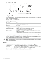
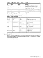
Figure 5-1 Control Panel LEDs Power and System LEDs The power and system LEDs indicate the state of the system. When the system LED is flashing yellow or red, a problem exists. Table 5-3 lists the system LED states. Table 5-3 System LED States System LED Off Solid green Flashing green Flashing yellow (1/sec.) Flashing red (2/sec.) State AC power is off if the power LED is off Running OS Booting or running BCH Attention: Alerts of levels 3-5 detected in the iLO MP logs The LED turns off once the event log has been read Fault: System Alert 7 detected, LED blinks until the problem is resolved and the system boots successfully Fatal hardware error detected by BMC, LED blinks until the problem is corrected For system alerts of levels 3-5, clear the attention condition on the LED. To access the logs, use the SL command available in the iLO MP command mode. The fault condition for system alerts of level 7 is cleared by resolving the problem and cycling power. For additional error information, see the SL error logs. NOTE: Before replacing any hardware, check the iLO MP status logs in the case of a flashing yellow or red system LED. LAN LEDs The front panel LAN LED indicates the system is communicating over the Gigabit: Flashing green The system is communicating over the LAN; the LAN is active. Not green No LAN cable is attached; LAN network is dead or the system is off or the LAN link is not established; no current LAN activity. Table 5-4 lists the 10/100/1000 base-T Ethernet LAN connectors LEDs. 118 Troubleshooting
-
 1
1 -
2
-
3
-
4
-
5
-
6
-
7
-
8
-
9
-
10
-
11
-
12
-
13
-
14
-
15
-
16
-
17
-
18
-
19
-
20
-
21
-
22
-
23
-
24
-
25
-
26
-
27
-
28
-
29
-
30
-
31
-
32
-
33
-
34
-
35
-
36
-
37
-
38
-
39
-
40
-
41
-
42
-
43
-
44
-
45
-
46
-
47
-
48
-
49
-
50
-
51
-
52
-
53
-
54
-
55
-
56
-
57
-
58
-
59
-
60
-
61
-
62
-
63
-
64
-
65
-
66
-
67
-
68
-
69
-
70
-
71
-
72
-
73
-
74
-
75
-
76
-
77
-
78
-
79
-
80
-
81
-
82
-
83
-
84
-
85
-
86
-
87
-
88
-
89
-
90
-
91
-
92
-
93
-
94
-
95
-
96
-
97
-
98
-
99
-
100
-
101
-
102
-
103
-
104
-
105
-
106
-
107
-
108
-
109
-
110
-
111
-
112
-
 113
113 -
 114
114 -
 115
115 -
 116
116 -
 117
117 -
 118
118 -
 119
119 -
 120
120 -
 121
121 -
 122
122 -
 123
123 -
124
-
125
-
126
-
127
-
128
-
129
-
130
-
131
-
132
-
133
-
134
-
135
-
136
-
137
-
138
-
139
-
140
-
141
-
142
-
143
-
144
-
145
-
146
-
147
-
148
-
149
-
150
-
151
-
152
-
153
-
154
-
155
-
156
-
157
-
158
-
159
-
160
-
161
-
162
-
163
-
164
-
165
-
166
-
167
-
168
-
169
-
170
-
171
-
172
-
173
-
174
-
175
-
176
-
177
-
178
-
179
-
180
-
181
-
182
-
183
-
184
-
185
-
186
-
187
-
188
-
189
-
190
-
191
-
192
-
193
-
194
-
195
-
196
-
197
-
198
-
199
-
200
-
201
-
202
-
203
-
204
-
205
-
206
-
207
-
208
-
209
-
210
 |
 |
