HP rp3440 User Service Guide, Sixth Edition - HP 9000 rp3410/rp3440 - Page 30
Table 1-4 Extended Core I/O Paths, Table 1-5 PCI I/O Paths, Table 1-6 PCI I/O Hardware Paths
 |
View all HP rp3440 manuals
Add to My Manuals
Save this manual to your list of manuals |
Page 30 highlights
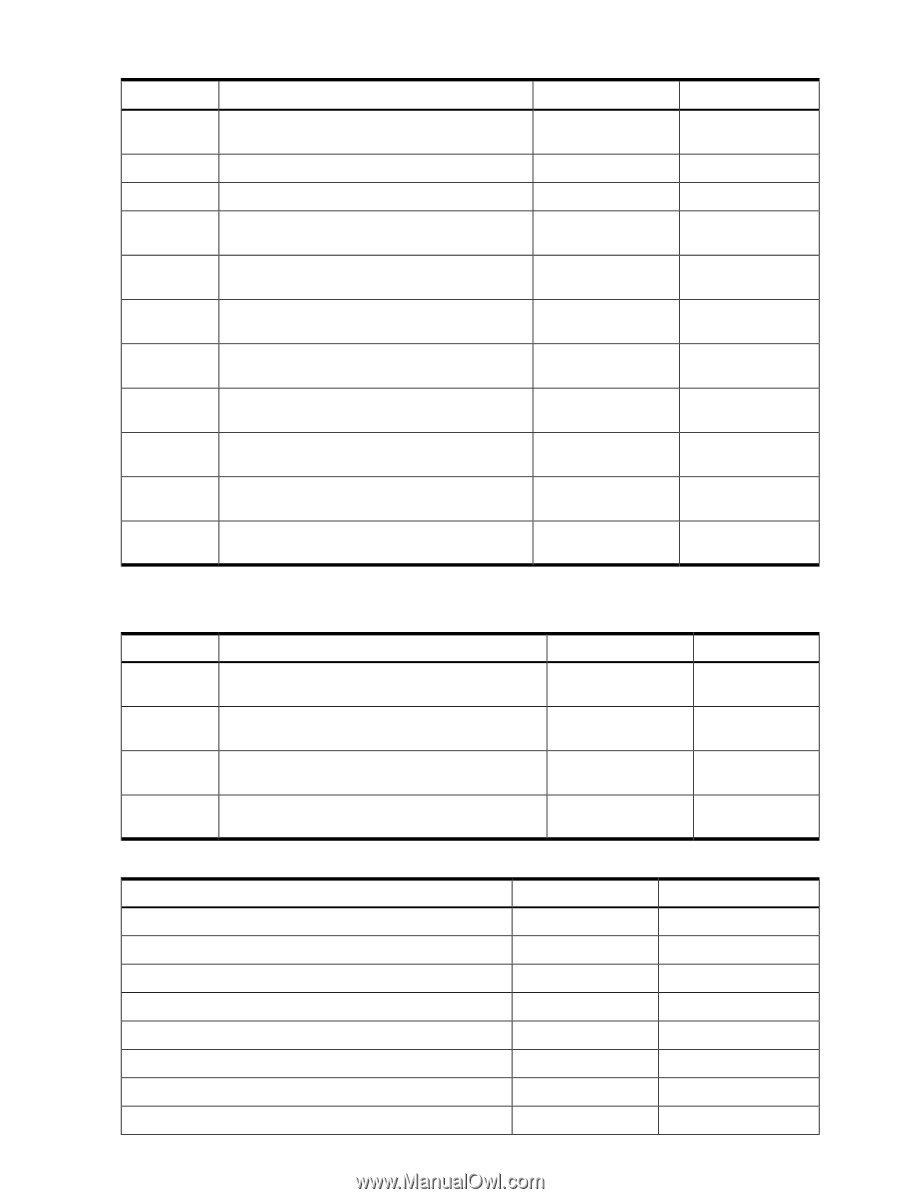
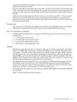
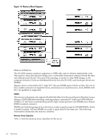
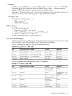
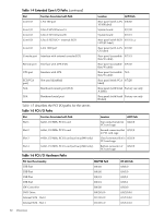
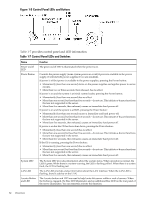
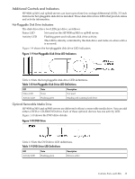
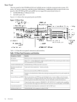
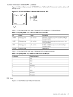
Table 1-4 Extended Core I/O Paths (continued) Slot Core I/O Function Associated with Path LAN 100 port Core I/O Core I/O Core I/O Ultra 3 SCSI Channel A Ultra 3 SCSI Channel B Ultra 3 SCSI I/O- external SCSI Core I/O LAN 1000 port Console port Interface with external console (ECI) Remote port Interface with UPS (ECI) UPS port Interface with UPS ECI (VGA port) N/A Not used (disabled) Baseboard console port (CLI) N/A Baseboard serial port Location ACPI Path Rear panel (with LAN 0/0/3/0 10/100 label) System board 0/1/1/0 System board 0/1/1/1 Rear panel (with SCSI 0/1/1/1.x.y LVD/SE label) Rear panel (with LAN 0/1/2/0 GV label) Rear panel (accessible 0/7/1/1 thru W cable) Rear panel (accessible 0/7/1/0 thru W cable) Rear panel (accessible N/A thru W cable) Rear panel (with VGA 0/7/2/0 label) Rear panel (with Serial Factory use only A label) Rear panel (with Serial Factory use only B label) Table 1-5 describes the PCI I/O paths for the server. Table 1-5 PCI I/O Paths Slot Slot 1 Slot 2 Slot 3 Slot 4 Function Associated with Path 64-bit, 133 MHz PCI-X card 64-bit, 133 MHz PCI-X card 64-bit, 133 MHz PCI-X card (active rp3440 only) 64-bit, 133 MHz PCI-X card (active rp3440 only) Location ACPI Path Top connector/slot in 0/4/1/0 PCI card cage Second connector/slot 0/3/1/0 in PCI card cage Third connector/slot in 0/2/1/0 PCI card cage Bottom connector of 0/6/1/0 PCI card cage Table 1-6 PCI I/O Hardware Paths PCI Card Functionality USB Port USB Port USB Port USB Port IDE Controller DVD Drive Internal SCSI - Slot 0 Internal SCSI - Slot 1 MAPPER Path 0/0/1/0 0/0/1/0 0/0/1/1 0/0/1/1 0/0/2/0 0/0/2/0.0.0 0/1/1/0.0.0 0/1/1/0.1.0 HP-UX Path 0/0/1/0 0/0/1/0 0/0/1/1 0/0/1/1 0/0/2/0 0/0/2/0.0.0 0/1/1/0.0.0 0/1/1/0.1.0 30 Overview
-
 1
1 -
2
-
3
-
4
-
5
-
6
-
7
-
8
-
9
-
10
-
11
-
12
-
13
-
14
-
15
-
16
-
17
-
18
-
19
-
20
-
21
-
22
-
23
-
24
-
 25
25 -
 26
26 -
 27
27 -
 28
28 -
 29
29 -
 30
30 -
 31
31 -
 32
32 -
 33
33 -
 34
34 -
 35
35 -
36
-
37
-
38
-
39
-
40
-
41
-
42
-
43
-
44
-
45
-
46
-
47
-
48
-
49
-
50
-
51
-
52
-
53
-
54
-
55
-
56
-
57
-
58
-
59
-
60
-
61
-
62
-
63
-
64
-
65
-
66
-
67
-
68
-
69
-
70
-
71
-
72
-
73
-
74
-
75
-
76
-
77
-
78
-
79
-
80
-
81
-
82
-
83
-
84
-
85
-
86
-
87
-
88
-
89
-
90
-
91
-
92
-
93
-
94
-
95
-
96
-
97
-
98
-
99
-
100
-
101
-
102
-
103
-
104
-
105
-
106
-
107
-
108
-
109
-
110
-
111
-
112
-
113
-
114
-
115
-
116
-
117
-
118
-
119
-
120
-
121
-
122
-
123
-
124
-
125
-
126
-
127
-
128
-
129
-
130
-
131
-
132
-
133
-
134
-
135
-
136
-
137
-
138
-
139
-
140
-
141
-
142
-
143
-
144
-
145
-
146
-
147
-
148
-
149
-
150
-
151
-
152
-
153
-
154
-
155
-
156
-
157
-
158
-
159
-
160
-
161
-
162
-
163
-
164
-
165
-
166
-
167
-
168
-
169
-
170
-
171
-
172
-
173
-
174
-
175
-
176
-
177
-
178
-
179
-
180
-
181
-
182
-
183
-
184
-
185
-
186
-
187
-
188
-
189
-
190
-
191
-
192
-
193
-
194
-
195
-
196
-
197
-
198
-
199
-
200
-
201
-
202
-
203
-
204
-
205
-
206
-
207
-
208
-
209
-
210
 |
 |