HP rp3440 User Service Guide, Sixth Edition - HP 9000 rp3410/rp3440 - Page 181
Aligning the System Board PCI Connector
 |
View all HP rp3440 manuals
Add to My Manuals
Save this manual to your list of manuals |
Page 181 highlights
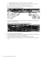
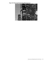
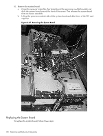
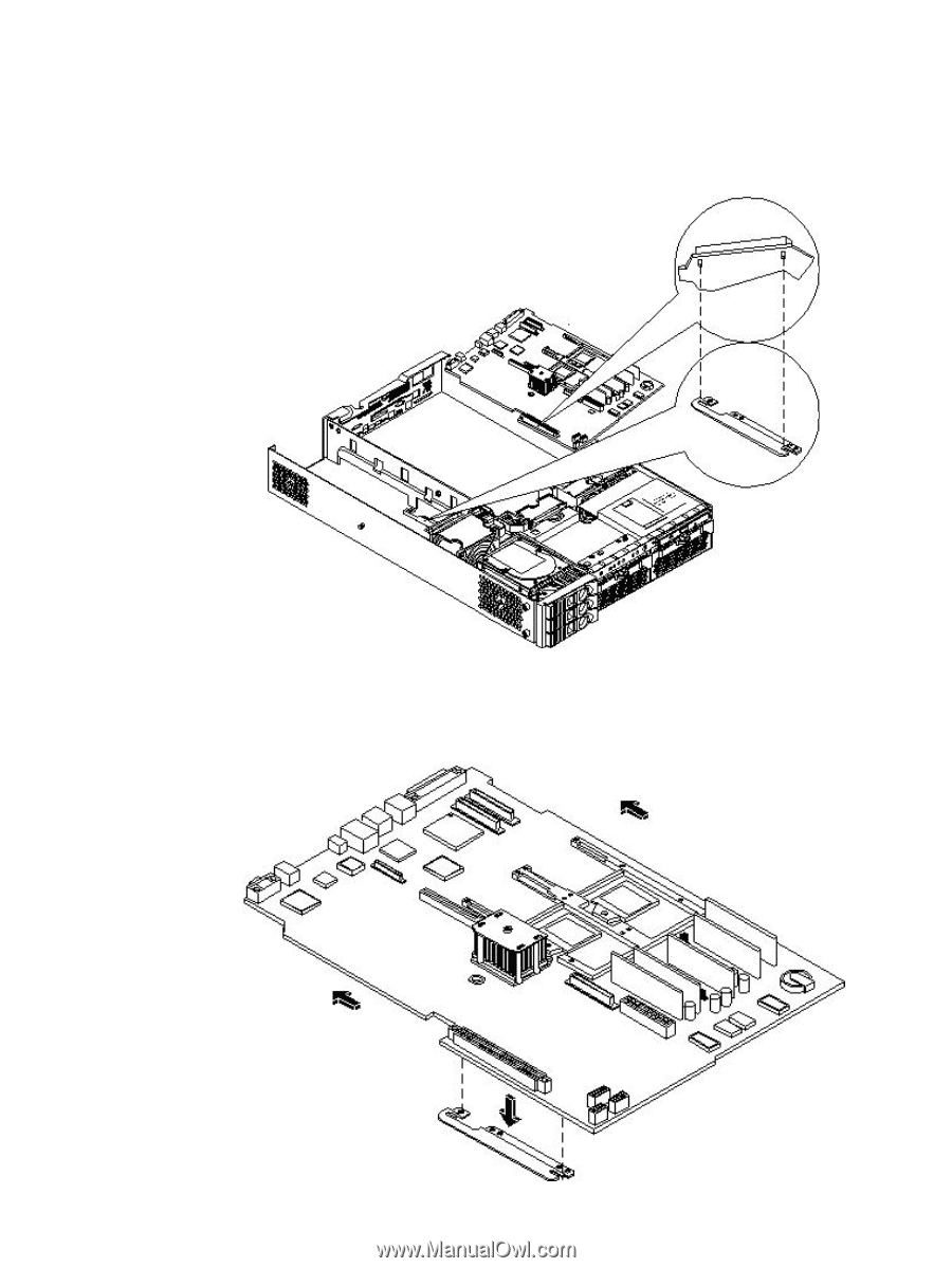
1. Grasp the new system board by its edges and carefully align it in the server: a. Angle the board to enable the PCI connector to slide into the PCI card cage bay area. b. Align the system board keyholes with their standoffs on the chassis. c. Slide the PCI connector posts on the system board into their slots on the server chassis. Figure 6-68 Aligning the System Board PCI Connector 2. Slide the system board back toward the rear of the server to secure the system board on its standoffs. Figure 6-69 Sliding the System Board in the Chassis Removing and Replacing the System Board 181
-
 1
1 -
2
-
3
-
4
-
5
-
6
-
7
-
8
-
9
-
10
-
11
-
12
-
13
-
14
-
15
-
16
-
17
-
18
-
19
-
20
-
21
-
22
-
23
-
24
-
25
-
26
-
27
-
28
-
29
-
30
-
31
-
32
-
33
-
34
-
35
-
36
-
37
-
38
-
39
-
40
-
41
-
42
-
43
-
44
-
45
-
46
-
47
-
48
-
49
-
50
-
51
-
52
-
53
-
54
-
55
-
56
-
57
-
58
-
59
-
60
-
61
-
62
-
63
-
64
-
65
-
66
-
67
-
68
-
69
-
70
-
71
-
72
-
73
-
74
-
75
-
76
-
77
-
78
-
79
-
80
-
81
-
82
-
83
-
84
-
85
-
86
-
87
-
88
-
89
-
90
-
91
-
92
-
93
-
94
-
95
-
96
-
97
-
98
-
99
-
100
-
101
-
102
-
103
-
104
-
105
-
106
-
107
-
108
-
109
-
110
-
111
-
112
-
113
-
114
-
115
-
116
-
117
-
118
-
119
-
120
-
121
-
122
-
123
-
124
-
125
-
126
-
127
-
128
-
129
-
130
-
131
-
132
-
133
-
134
-
135
-
136
-
137
-
138
-
139
-
140
-
141
-
142
-
143
-
144
-
145
-
146
-
147
-
148
-
149
-
150
-
151
-
152
-
153
-
154
-
155
-
156
-
157
-
158
-
159
-
160
-
161
-
162
-
163
-
164
-
165
-
166
-
167
-
168
-
169
-
170
-
171
-
172
-
173
-
174
-
175
-
 176
176 -
 177
177 -
 178
178 -
 179
179 -
 180
180 -
 181
181 -
 182
182 -
 183
183 -
 184
184 -
 185
185 -
 186
186 -
187
-
188
-
189
-
190
-
191
-
192
-
193
-
194
-
195
-
196
-
197
-
198
-
199
-
200
-
201
-
202
-
203
-
204
-
205
-
206
-
207
-
208
-
209
-
210
 |
 |
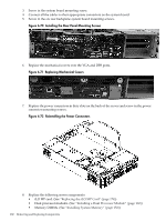
1.
Grasp the new system board by its edges and carefully align it in the server:
a.
Angle the board to enable the PCI connector to slide into the PCI card cage bay area.
b.
Align the system board keyholes with their standoffs on the chassis.
c.
Slide the PCI connector posts on the system board into their slots on the server chassis.
Figure 6-68 Aligning the System Board PCI Connector
2.
Slide the system board back toward the rear of the server to secure the system board on its
standoffs.
Figure 6-69 Sliding the System Board in the Chassis
Removing and Replacing the System Board
181