HP rp3440 User Service Guide, Sixth Edition - HP 9000 rp3410/rp3440 - Page 158
Releasing the Heatsink Captive Screws
 |
View all HP rp3440 manuals
Add to My Manuals
Save this manual to your list of manuals |
Page 158 highlights
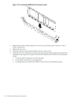
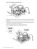
Figure 6-40 Releasing the Heatsink Captive Screws 11. Slide the sequencing retainer plate toward the back of the server to open the hole in the edge of the heatsink for insertion of the special processor tool into the processor module locking mechanism. 12. Unlock the dual processor module locking mechanism using the CPU install tool. Insert the tool into the hole that runs down through the edge of the turbo fan heatsink and rotate the special processor tool 180 degrees counterclockwise. Figure 6-41 Unlocking the Dual Processor Module Locking Mechanism 158 Removing and Replacing Components
-
 1
1 -
2
-
3
-
4
-
5
-
6
-
7
-
8
-
9
-
10
-
11
-
12
-
13
-
14
-
15
-
16
-
17
-
18
-
19
-
20
-
21
-
22
-
23
-
24
-
25
-
26
-
27
-
28
-
29
-
30
-
31
-
32
-
33
-
34
-
35
-
36
-
37
-
38
-
39
-
40
-
41
-
42
-
43
-
44
-
45
-
46
-
47
-
48
-
49
-
50
-
51
-
52
-
53
-
54
-
55
-
56
-
57
-
58
-
59
-
60
-
61
-
62
-
63
-
64
-
65
-
66
-
67
-
68
-
69
-
70
-
71
-
72
-
73
-
74
-
75
-
76
-
77
-
78
-
79
-
80
-
81
-
82
-
83
-
84
-
85
-
86
-
87
-
88
-
89
-
90
-
91
-
92
-
93
-
94
-
95
-
96
-
97
-
98
-
99
-
100
-
101
-
102
-
103
-
104
-
105
-
106
-
107
-
108
-
109
-
110
-
111
-
112
-
113
-
114
-
115
-
116
-
117
-
118
-
119
-
120
-
121
-
122
-
123
-
124
-
125
-
126
-
127
-
128
-
129
-
130
-
131
-
132
-
133
-
134
-
135
-
136
-
137
-
138
-
139
-
140
-
141
-
142
-
143
-
144
-
145
-
146
-
147
-
148
-
149
-
150
-
151
-
152
-
 153
153 -
 154
154 -
 155
155 -
 156
156 -
 157
157 -
 158
158 -
 159
159 -
 160
160 -
 161
161 -
 162
162 -
 163
163 -
164
-
165
-
166
-
167
-
168
-
169
-
170
-
171
-
172
-
173
-
174
-
175
-
176
-
177
-
178
-
179
-
180
-
181
-
182
-
183
-
184
-
185
-
186
-
187
-
188
-
189
-
190
-
191
-
192
-
193
-
194
-
195
-
196
-
197
-
198
-
199
-
200
-
201
-
202
-
203
-
204
-
205
-
206
-
207
-
208
-
209
-
210
 |
 |
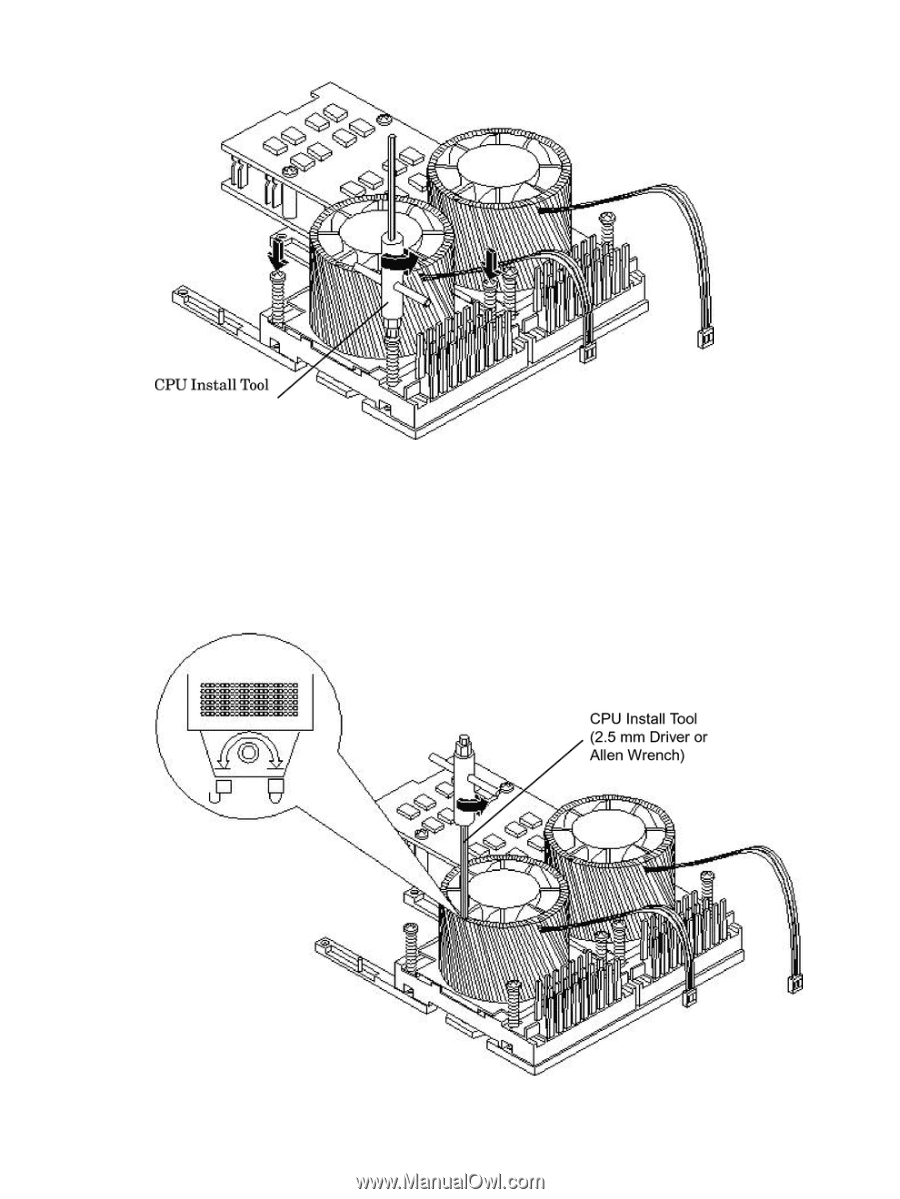
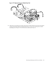
Figure 6-40 Releasing the Heatsink Captive Screws
11.
Slide the sequencing retainer plate toward the back of the server to open the hole in the edge
of the heatsink for insertion of the special processor tool into the processor module locking
mechanism.
12.
Unlock the dual processor module locking mechanism using the CPU install tool. Insert the
tool into the hole that runs down through the edge of the turbo fan heatsink and rotate the
special processor tool 180 degrees counterclockwise.
Figure 6-41 Unlocking the Dual Processor Module Locking Mechanism
158
Removing and Replacing Components