HP rp3440 User Service Guide, Sixth Edition - HP 9000 rp3410/rp3440 - Page 162
Securing the Captive Screws, Power Module Shims
 |
View all HP rp3440 manuals
Add to My Manuals
Save this manual to your list of manuals |
Page 162 highlights
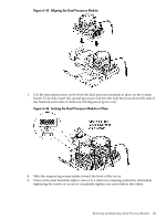
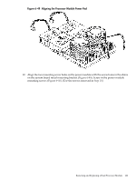
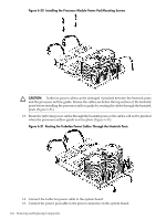
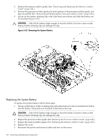
Figure 6-47 Securing the Captive Screws 10. If you are installing a second dual processor module in a server which contained only one dual processor module, remove the spacers from the power module mounting: (Figure 6-48.) a. Locate the two power module shims on the system board. b. Remove the holding screws that hold the shims in place. c. Remove the spacers from the holding screws. Discard the spacers. d. Retain the screws for use when installing the power module. Figure 6-48 Power Module Shims 11. Slide the power module on the system board metal mounting bracket so that the connector on the power module makes contact with its connector on the dual processor module. 162 Removing and Replacing Components
-
 1
1 -
2
-
3
-
4
-
5
-
6
-
7
-
8
-
9
-
10
-
11
-
12
-
13
-
14
-
15
-
16
-
17
-
18
-
19
-
20
-
21
-
22
-
23
-
24
-
25
-
26
-
27
-
28
-
29
-
30
-
31
-
32
-
33
-
34
-
35
-
36
-
37
-
38
-
39
-
40
-
41
-
42
-
43
-
44
-
45
-
46
-
47
-
48
-
49
-
50
-
51
-
52
-
53
-
54
-
55
-
56
-
57
-
58
-
59
-
60
-
61
-
62
-
63
-
64
-
65
-
66
-
67
-
68
-
69
-
70
-
71
-
72
-
73
-
74
-
75
-
76
-
77
-
78
-
79
-
80
-
81
-
82
-
83
-
84
-
85
-
86
-
87
-
88
-
89
-
90
-
91
-
92
-
93
-
94
-
95
-
96
-
97
-
98
-
99
-
100
-
101
-
102
-
103
-
104
-
105
-
106
-
107
-
108
-
109
-
110
-
111
-
112
-
113
-
114
-
115
-
116
-
117
-
118
-
119
-
120
-
121
-
122
-
123
-
124
-
125
-
126
-
127
-
128
-
129
-
130
-
131
-
132
-
133
-
134
-
135
-
136
-
137
-
138
-
139
-
140
-
141
-
142
-
143
-
144
-
145
-
146
-
147
-
148
-
149
-
150
-
151
-
152
-
153
-
154
-
155
-
156
-
 157
157 -
 158
158 -
 159
159 -
 160
160 -
 161
161 -
 162
162 -
 163
163 -
 164
164 -
 165
165 -
 166
166 -
 167
167 -
168
-
169
-
170
-
171
-
172
-
173
-
174
-
175
-
176
-
177
-
178
-
179
-
180
-
181
-
182
-
183
-
184
-
185
-
186
-
187
-
188
-
189
-
190
-
191
-
192
-
193
-
194
-
195
-
196
-
197
-
198
-
199
-
200
-
201
-
202
-
203
-
204
-
205
-
206
-
207
-
208
-
209
-
210
 |
 |
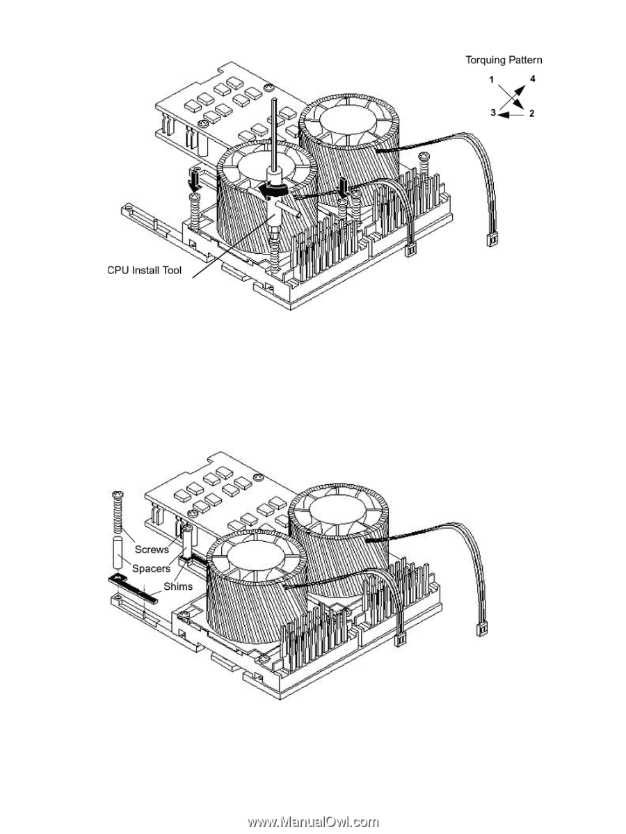
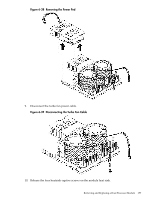
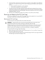
Figure 6-47 Securing the Captive Screws
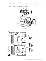
10.
If you are installing a second dual processor module in a server which contained only one
dual processor module, remove the spacers from the power module mounting: (
Figure 6-48
.)
a.
Locate the two power module shims on the system board.
b.
Remove the holding screws that hold the shims in place.
c.
Remove the spacers from the holding screws. Discard the spacers.
d.
Retain the screws for use when installing the power module.
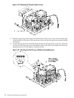
Figure 6-48 Power Module Shims
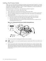
11.
Slide the power module on the system board metal mounting bracket so that the connector
on the power module makes contact with its connector on the dual processor module.
162
Removing and Replacing Components