HP rp3440 User Service Guide, Sixth Edition - HP 9000 rp3410/rp3440 - Page 75
Replacing the PCI Card Cage, Installing PCI Cards
 |
View all HP rp3440 manuals
Add to My Manuals
Save this manual to your list of manuals |
Page 75 highlights
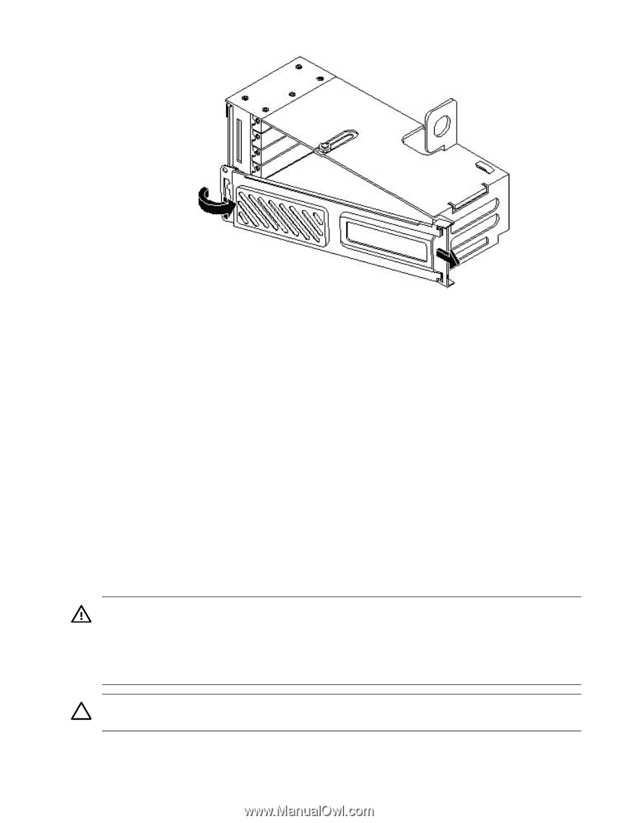
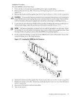
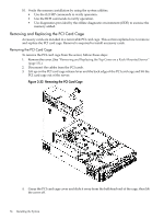
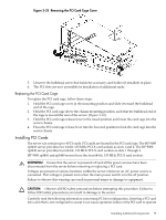
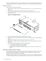
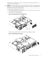
Figure 3-33 Removing the PCI Card Cage Cover 5. Unscrew the bulkhead screw that holds the accessory card holder (if installed) in place. 6. The PCI slots are now accessible for installation of additional cards. Replacing the PCI Card Cage To replace the PCI card cage, follow these steps: 1. Hold the PCI card cage cover in the mounting position and slide it toward the bulkhead end of the cage. 2. Hold the PCI card cage above the chassis mounting position, such that the bulkhead end of the cage is toward the rear of the server. (Figure 3-32.) 3. Hold the PCI card cage release lever in the raised position and lower the card cage into the server chassis. 4. Press the PCI card cage release lever into the lowered position to lock the card cage into the server chassis. Installing PCI Cards The server can contain up to 4 PCI cards. PCI cards are located in the PCI card cage. The HP 9000 rp3410 server provides two 64-bit, 133 MHz PCI-X card sockets as slots 1 and 2. The HP 9000 rp3440 server provides four 64-bit, 133 MHz PCI-X card sockets as slots 1 through 4. HP 9000 rp3410 and rp3440 servers have the four 64-bit, 133 MHz PCI-X card sockets. WARNING! Ensure that the server is powered off and all the power sources have been disconnected from the server before removing or replacing a PCI card. Voltages are present at various locations within the server whenever an AC power source is connected. This voltage is present even when the main power switch is in the off position. Failure to observe this warning can result in personal injury or damage to equipment. CAUTION: Observe all ESD safety precautions before attempting this procedure. Failure to follow ESD safety precautions can result in damage to the server. Carefully read the following information concerning PCI slot configuration. Inserting a PCI card into a slot that is not configured to accept it can cause operation failure or the PCI card to operate Installing Additional Components 75
-
 1
1 -
2
-
3
-
4
-
5
-
6
-
7
-
8
-
9
-
10
-
11
-
12
-
13
-
14
-
15
-
16
-
17
-
18
-
19
-
20
-
21
-
22
-
23
-
24
-
25
-
26
-
27
-
28
-
29
-
30
-
31
-
32
-
33
-
34
-
35
-
36
-
37
-
38
-
39
-
40
-
41
-
42
-
43
-
44
-
45
-
46
-
47
-
48
-
49
-
50
-
51
-
52
-
53
-
54
-
55
-
56
-
57
-
58
-
59
-
60
-
61
-
62
-
63
-
64
-
65
-
66
-
67
-
68
-
69
-
 70
70 -
 71
71 -
 72
72 -
 73
73 -
 74
74 -
 75
75 -
 76
76 -
 77
77 -
 78
78 -
 79
79 -
 80
80 -
81
-
82
-
83
-
84
-
85
-
86
-
87
-
88
-
89
-
90
-
91
-
92
-
93
-
94
-
95
-
96
-
97
-
98
-
99
-
100
-
101
-
102
-
103
-
104
-
105
-
106
-
107
-
108
-
109
-
110
-
111
-
112
-
113
-
114
-
115
-
116
-
117
-
118
-
119
-
120
-
121
-
122
-
123
-
124
-
125
-
126
-
127
-
128
-
129
-
130
-
131
-
132
-
133
-
134
-
135
-
136
-
137
-
138
-
139
-
140
-
141
-
142
-
143
-
144
-
145
-
146
-
147
-
148
-
149
-
150
-
151
-
152
-
153
-
154
-
155
-
156
-
157
-
158
-
159
-
160
-
161
-
162
-
163
-
164
-
165
-
166
-
167
-
168
-
169
-
170
-
171
-
172
-
173
-
174
-
175
-
176
-
177
-
178
-
179
-
180
-
181
-
182
-
183
-
184
-
185
-
186
-
187
-
188
-
189
-
190
-
191
-
192
-
193
-
194
-
195
-
196
-
197
-
198
-
199
-
200
-
201
-
202
-
203
-
204
-
205
-
206
-
207
-
208
-
209
-
210
 |
 |