HP rp3440 User Service Guide, Sixth Edition - HP 9000 rp3410/rp3440 - Page 24
System Board Components, PA RISC Processor, System Board Block Diagram
 |
View all HP rp3440 manuals
Add to My Manuals
Save this manual to your list of manuals |
Page 24 highlights
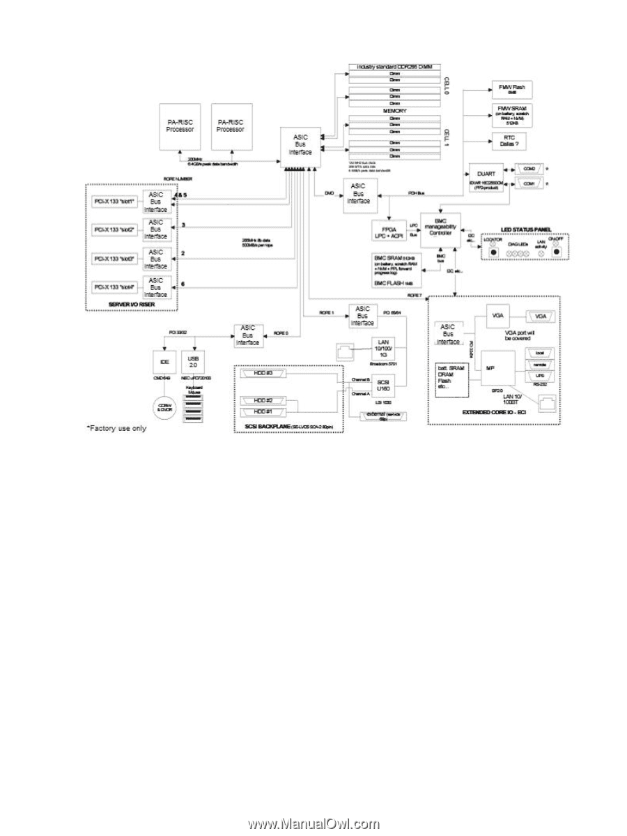
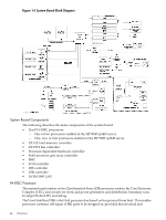
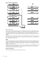
Figure 1-5 System Board Block Diagram System Board Components The following describes the main components of the system board: • Dual PA-RISC processors: - One or two processors enabled in the HP 9000 rp3410 server - One, two, or four processors enabled in the HP 9000 rp3440 server • ZX1 I/O and memory controller • ZX1 PCI bus controller • Processor dependent hardware controller • Field processor gate array controller • BMC • SCSI controller • IDE controller • USB controller • 10/100/1000 LAN PA RISC Processor The system board consists of two Zero Insertion Force (ZIF) processor sockets, the Core Electronic Complex (CEC), and circuits for clock and power generation and distribution, boundary scan, In-target Probe (ITP), and debug. The Front Side Bus (FSB) is the IA64 processor bus based on bus protocol from Intel. This enables processor customer self-repair (CSR) parts to be dropped in, provided that electrical and 24 Overview
-
 1
1 -
2
-
3
-
4
-
5
-
6
-
7
-
8
-
9
-
10
-
11
-
12
-
13
-
14
-
15
-
16
-
17
-
18
-
 19
19 -
 20
20 -
 21
21 -
 22
22 -
 23
23 -
 24
24 -
 25
25 -
 26
26 -
 27
27 -
 28
28 -
 29
29 -
30
-
31
-
32
-
33
-
34
-
35
-
36
-
37
-
38
-
39
-
40
-
41
-
42
-
43
-
44
-
45
-
46
-
47
-
48
-
49
-
50
-
51
-
52
-
53
-
54
-
55
-
56
-
57
-
58
-
59
-
60
-
61
-
62
-
63
-
64
-
65
-
66
-
67
-
68
-
69
-
70
-
71
-
72
-
73
-
74
-
75
-
76
-
77
-
78
-
79
-
80
-
81
-
82
-
83
-
84
-
85
-
86
-
87
-
88
-
89
-
90
-
91
-
92
-
93
-
94
-
95
-
96
-
97
-
98
-
99
-
100
-
101
-
102
-
103
-
104
-
105
-
106
-
107
-
108
-
109
-
110
-
111
-
112
-
113
-
114
-
115
-
116
-
117
-
118
-
119
-
120
-
121
-
122
-
123
-
124
-
125
-
126
-
127
-
128
-
129
-
130
-
131
-
132
-
133
-
134
-
135
-
136
-
137
-
138
-
139
-
140
-
141
-
142
-
143
-
144
-
145
-
146
-
147
-
148
-
149
-
150
-
151
-
152
-
153
-
154
-
155
-
156
-
157
-
158
-
159
-
160
-
161
-
162
-
163
-
164
-
165
-
166
-
167
-
168
-
169
-
170
-
171
-
172
-
173
-
174
-
175
-
176
-
177
-
178
-
179
-
180
-
181
-
182
-
183
-
184
-
185
-
186
-
187
-
188
-
189
-
190
-
191
-
192
-
193
-
194
-
195
-
196
-
197
-
198
-
199
-
200
-
201
-
202
-
203
-
204
-
205
-
206
-
207
-
208
-
209
-
210
 |
 |