HP rp3440 User Service Guide, Sixth Edition - HP 9000 rp3410/rp3440 - Page 79
Unlocking the Dual Processor Module Locking Mechanism, saved for future use.
 |
View all HP rp3440 manuals
Add to My Manuals
Save this manual to your list of manuals |
Page 79 highlights
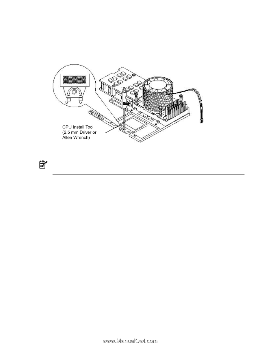
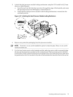
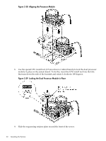
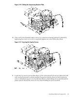
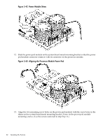
5. Unlock the dual processor module locking mechanism using the CPU install tool (2.5 mm driver or Allen Wrench). a. Insert the tool into the hole that runs down through the edge of the heatsink and rotate the special processor tool 180 degrees counterclockwise. b. Verify that the dual processor module socket locking mechanism is rotated into the unlocked position. Figure 3-37 Unlocking the Dual Processor Module Locking Mechanism 6. Remove any protective packaging from the processor module. NOTE: Protective covers can be installed to protect connector pins. These covers can be saved for future use. 7. Use the four locator posts on the heatsink and the turbo fan power cable to properly align the fan and dual processor module on the system board. The four locator posts will fit in locator holes on the system board processor module mount. The turbo fan power cable must be positioned so that it is located on the side of the heatsink that faces the front of the server. Installing Additional Components 79
-
 1
1 -
2
-
3
-
4
-
5
-
6
-
7
-
8
-
9
-
10
-
11
-
12
-
13
-
14
-
15
-
16
-
17
-
18
-
19
-
20
-
21
-
22
-
23
-
24
-
25
-
26
-
27
-
28
-
29
-
30
-
31
-
32
-
33
-
34
-
35
-
36
-
37
-
38
-
39
-
40
-
41
-
42
-
43
-
44
-
45
-
46
-
47
-
48
-
49
-
50
-
51
-
52
-
53
-
54
-
55
-
56
-
57
-
58
-
59
-
60
-
61
-
62
-
63
-
64
-
65
-
66
-
67
-
68
-
69
-
70
-
71
-
72
-
73
-
 74
74 -
 75
75 -
 76
76 -
 77
77 -
 78
78 -
 79
79 -
 80
80 -
 81
81 -
 82
82 -
 83
83 -
 84
84 -
85
-
86
-
87
-
88
-
89
-
90
-
91
-
92
-
93
-
94
-
95
-
96
-
97
-
98
-
99
-
100
-
101
-
102
-
103
-
104
-
105
-
106
-
107
-
108
-
109
-
110
-
111
-
112
-
113
-
114
-
115
-
116
-
117
-
118
-
119
-
120
-
121
-
122
-
123
-
124
-
125
-
126
-
127
-
128
-
129
-
130
-
131
-
132
-
133
-
134
-
135
-
136
-
137
-
138
-
139
-
140
-
141
-
142
-
143
-
144
-
145
-
146
-
147
-
148
-
149
-
150
-
151
-
152
-
153
-
154
-
155
-
156
-
157
-
158
-
159
-
160
-
161
-
162
-
163
-
164
-
165
-
166
-
167
-
168
-
169
-
170
-
171
-
172
-
173
-
174
-
175
-
176
-
177
-
178
-
179
-
180
-
181
-
182
-
183
-
184
-
185
-
186
-
187
-
188
-
189
-
190
-
191
-
192
-
193
-
194
-
195
-
196
-
197
-
198
-
199
-
200
-
201
-
202
-
203
-
204
-
205
-
206
-
207
-
208
-
209
-
210
 |
 |