HP rp3440 User Service Guide, Sixth Edition - HP 9000 rp3410/rp3440 - Page 155
Removing and Replacing a Dual Processor Module, Removing a Dual Processor Module
 |
View all HP rp3440 manuals
Add to My Manuals
Save this manual to your list of manuals |
Page 155 highlights
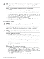
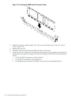
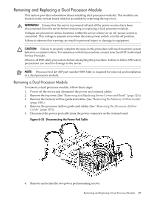
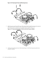
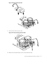
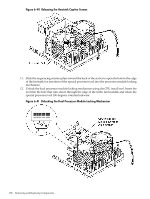
Removing and Replacing a Dual Processor Module This section provides information about installing dual processor modules. The modules are located on the system board which is accessible by removing the top cover. WARNING! Ensure that the server is powered off and all the power sources have been disconnected from the server before removing or replacing a dual processor module. Voltages are present at various locations within the server whenever an AC power source is connected. This voltage is present even when the main power switch is in the off position. Failure to observe this warning can result in personal injury or damage to equipment. CAUTION: Failure to properly complete the steps in this procedure will result in erratic system behavior or system failure. For assistance with this procedure, contact your local HP Authorized Service Provider. Observe all ESD safety precautions before attempting this procedure. Failure to follow ESD safety precautions can result in damage to the server. NOTE: Processor tool kit (HP part number 5069-5441) is required for removal and installation of a dual processor module. Removing a Dual Processor Module To remove a dual processor module, follow these steps: 1. Power off the server and disconnect the power and external cables. 2. Remove the top cover. (See "Removing and Replacing Server Covers and Bezel" (page 126).) 3. Remove the memory airflow guide and cables. (See "Removing the Memory Airflow Guide" (page 144).) 4. Remove the processor airflow guide and cables. (See "Removing the Processor Airflow Guide" (page 145).) 5. Disconnect the power pod cable from the power connector on the system board Figure 6-35 Disconnecting the Power Pod Cable 6. Remove and retain the two power pod mounting screws. Removing and Replacing a Dual Processor Module 155
-
 1
1 -
2
-
3
-
4
-
5
-
6
-
7
-
8
-
9
-
10
-
11
-
12
-
13
-
14
-
15
-
16
-
17
-
18
-
19
-
20
-
21
-
22
-
23
-
24
-
25
-
26
-
27
-
28
-
29
-
30
-
31
-
32
-
33
-
34
-
35
-
36
-
37
-
38
-
39
-
40
-
41
-
42
-
43
-
44
-
45
-
46
-
47
-
48
-
49
-
50
-
51
-
52
-
53
-
54
-
55
-
56
-
57
-
58
-
59
-
60
-
61
-
62
-
63
-
64
-
65
-
66
-
67
-
68
-
69
-
70
-
71
-
72
-
73
-
74
-
75
-
76
-
77
-
78
-
79
-
80
-
81
-
82
-
83
-
84
-
85
-
86
-
87
-
88
-
89
-
90
-
91
-
92
-
93
-
94
-
95
-
96
-
97
-
98
-
99
-
100
-
101
-
102
-
103
-
104
-
105
-
106
-
107
-
108
-
109
-
110
-
111
-
112
-
113
-
114
-
115
-
116
-
117
-
118
-
119
-
120
-
121
-
122
-
123
-
124
-
125
-
126
-
127
-
128
-
129
-
130
-
131
-
132
-
133
-
134
-
135
-
136
-
137
-
138
-
139
-
140
-
141
-
142
-
143
-
144
-
145
-
146
-
147
-
148
-
149
-
 150
150 -
 151
151 -
 152
152 -
 153
153 -
 154
154 -
 155
155 -
 156
156 -
 157
157 -
 158
158 -
 159
159 -
 160
160 -
161
-
162
-
163
-
164
-
165
-
166
-
167
-
168
-
169
-
170
-
171
-
172
-
173
-
174
-
175
-
176
-
177
-
178
-
179
-
180
-
181
-
182
-
183
-
184
-
185
-
186
-
187
-
188
-
189
-
190
-
191
-
192
-
193
-
194
-
195
-
196
-
197
-
198
-
199
-
200
-
201
-
202
-
203
-
204
-
205
-
206
-
207
-
208
-
209
-
210
 |
 |