HP rp3440 User Service Guide, Sixth Edition - HP 9000 rp3410/rp3440 - Page 177
Replacing the LED Status Panel, Removing and Replacing the System Board, Removing the System Board
 |
View all HP rp3440 manuals
Add to My Manuals
Save this manual to your list of manuals |
Page 177 highlights
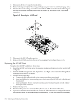
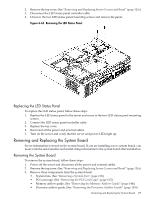
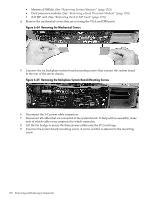
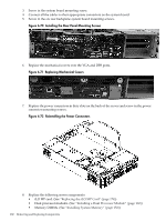
2. Remove the top cover. (See "Removing and Replacing Server Covers and Bezel" (page 126).) 3. Disconnect the LED status panel controller cable. 4. Unscrew the two LED status panel mounting screws and remove the panel. Figure 6-63 Removing the LED Status Panel Replacing the LED Status Panel To replace the LED status panel, follow these steps: 1. Replace the LED status panel in the server and screw in the two LED status panel mounting screws. 2. Connect the LED status panel controller cable. 3. Replace the top cover. 4. Reconnect all the power and external cables. 5. Turn on the server and verify that the server and power LEDs light up. Removing and Replacing the System Board Server information is stored on the system board. If you are installing a new system board, you must write the serial number and model string information to the system board after installation. Removing the System Board To remove the system board, follow these steps: 1. Power off the server and disconnect all the power and external cables. 2. Remove the top cover. (See "Removing and Replacing Server Covers and Bezel" (page 126).) 3. Remove these components from the system board: • System fans. (See "Removing a System Fan" (page 136)) • PCI card cage. (See "Removing the PCI Card Cage" (page 167)) • Memory airflow guide. (See "Removing the Memory Airflow Guide" (page 144)) • Processor airflow guide. (See "Removing the Processor Airflow Guide" (page 145)) Removing and Replacing the System Board 177
-
 1
1 -
2
-
3
-
4
-
5
-
6
-
7
-
8
-
9
-
10
-
11
-
12
-
13
-
14
-
15
-
16
-
17
-
18
-
19
-
20
-
21
-
22
-
23
-
24
-
25
-
26
-
27
-
28
-
29
-
30
-
31
-
32
-
33
-
34
-
35
-
36
-
37
-
38
-
39
-
40
-
41
-
42
-
43
-
44
-
45
-
46
-
47
-
48
-
49
-
50
-
51
-
52
-
53
-
54
-
55
-
56
-
57
-
58
-
59
-
60
-
61
-
62
-
63
-
64
-
65
-
66
-
67
-
68
-
69
-
70
-
71
-
72
-
73
-
74
-
75
-
76
-
77
-
78
-
79
-
80
-
81
-
82
-
83
-
84
-
85
-
86
-
87
-
88
-
89
-
90
-
91
-
92
-
93
-
94
-
95
-
96
-
97
-
98
-
99
-
100
-
101
-
102
-
103
-
104
-
105
-
106
-
107
-
108
-
109
-
110
-
111
-
112
-
113
-
114
-
115
-
116
-
117
-
118
-
119
-
120
-
121
-
122
-
123
-
124
-
125
-
126
-
127
-
128
-
129
-
130
-
131
-
132
-
133
-
134
-
135
-
136
-
137
-
138
-
139
-
140
-
141
-
142
-
143
-
144
-
145
-
146
-
147
-
148
-
149
-
150
-
151
-
152
-
153
-
154
-
155
-
156
-
157
-
158
-
159
-
160
-
161
-
162
-
163
-
164
-
165
-
166
-
167
-
168
-
169
-
170
-
171
-
 172
172 -
 173
173 -
 174
174 -
 175
175 -
 176
176 -
 177
177 -
 178
178 -
 179
179 -
 180
180 -
 181
181 -
 182
182 -
183
-
184
-
185
-
186
-
187
-
188
-
189
-
190
-
191
-
192
-
193
-
194
-
195
-
196
-
197
-
198
-
199
-
200
-
201
-
202
-
203
-
204
-
205
-
206
-
207
-
208
-
209
-
210
 |
 |
