HP rp3440 User Service Guide, Sixth Edition - HP 9000 rp3410/rp3440 - Page 31
Controls, Ports, and LEDs, Control Panel
 |
View all HP rp3440 manuals
Add to My Manuals
Save this manual to your list of manuals |
Page 31 highlights
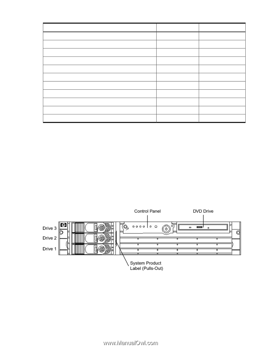
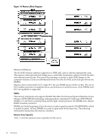
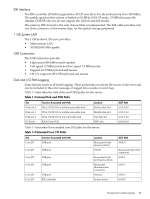
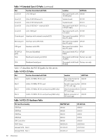
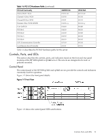
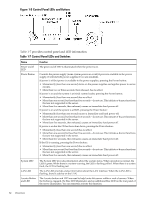
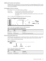
Table 1-6 PCI I/O Hardware Paths (continued) PCI Card Functionality Internal SCSI - Slot 2 Channel A Ultra 3 SCSI Channel B Ultra 3 SCSI External, Ultra 3 SCSI LVD/SE Core LAN Gb PCI Slot 1 PCI Slot 2 PCI Slot 3 PCI Slot 4 UPS, Communications Controller Local/Remote Serial Controller MAPPER Path 0/1/1/1.2.0 0/1/1/0 0/1/1/1 0/1/1/1.x.y 0/1/2/0 0/4/1/0 0/3/1/0 0/2/1/0 0/6/1/0 0/7/1/0 0/7/1/1 HP-UX Path 0/1/1/1.2.0 0/1/1/0 0/1/1/1 0/1/1/1.x.y 0/1/2/0 0/4/1/0 0/3/1/0 0/2/1/0 0/6/1/0 0/7/1/0 0/7/1/1 Table 1-6 describes the PCI I/O hardware paths for the server. Controls, Ports, and LEDs This section describes the controls, ports, and indicators found on the front and rear panel locations of the HP 9000 rp3410 or rp3440 server. The servers are designed to be rack- or pedestal-mounted. Control Panel The control panel of the HP 9000 rp3410 and rp3440 servers provide the controls and indicators commonly used for operation. Figure 1-7 shows the front panel details. Figure 1-7 Front View Figure 1-8 shows the control panel LEDs and buttons. Controls, Ports, and LEDs 31
-
 1
1 -
2
-
3
-
4
-
5
-
6
-
7
-
8
-
9
-
10
-
11
-
12
-
13
-
14
-
15
-
16
-
17
-
18
-
19
-
20
-
21
-
22
-
23
-
24
-
25
-
 26
26 -
 27
27 -
 28
28 -
 29
29 -
 30
30 -
 31
31 -
 32
32 -
 33
33 -
 34
34 -
 35
35 -
 36
36 -
37
-
38
-
39
-
40
-
41
-
42
-
43
-
44
-
45
-
46
-
47
-
48
-
49
-
50
-
51
-
52
-
53
-
54
-
55
-
56
-
57
-
58
-
59
-
60
-
61
-
62
-
63
-
64
-
65
-
66
-
67
-
68
-
69
-
70
-
71
-
72
-
73
-
74
-
75
-
76
-
77
-
78
-
79
-
80
-
81
-
82
-
83
-
84
-
85
-
86
-
87
-
88
-
89
-
90
-
91
-
92
-
93
-
94
-
95
-
96
-
97
-
98
-
99
-
100
-
101
-
102
-
103
-
104
-
105
-
106
-
107
-
108
-
109
-
110
-
111
-
112
-
113
-
114
-
115
-
116
-
117
-
118
-
119
-
120
-
121
-
122
-
123
-
124
-
125
-
126
-
127
-
128
-
129
-
130
-
131
-
132
-
133
-
134
-
135
-
136
-
137
-
138
-
139
-
140
-
141
-
142
-
143
-
144
-
145
-
146
-
147
-
148
-
149
-
150
-
151
-
152
-
153
-
154
-
155
-
156
-
157
-
158
-
159
-
160
-
161
-
162
-
163
-
164
-
165
-
166
-
167
-
168
-
169
-
170
-
171
-
172
-
173
-
174
-
175
-
176
-
177
-
178
-
179
-
180
-
181
-
182
-
183
-
184
-
185
-
186
-
187
-
188
-
189
-
190
-
191
-
192
-
193
-
194
-
195
-
196
-
197
-
198
-
199
-
200
-
201
-
202
-
203
-
204
-
205
-
206
-
207
-
208
-
209
-
210
 |
 |