HP rp3440 User Service Guide, Sixth Edition - HP 9000 rp3410/rp3440 - Page 182
Installing the Rear Panel Mounting Screws, Replacing Mechanical Covers
 |
View all HP rp3440 manuals
Add to My Manuals
Save this manual to your list of manuals |
Page 182 highlights
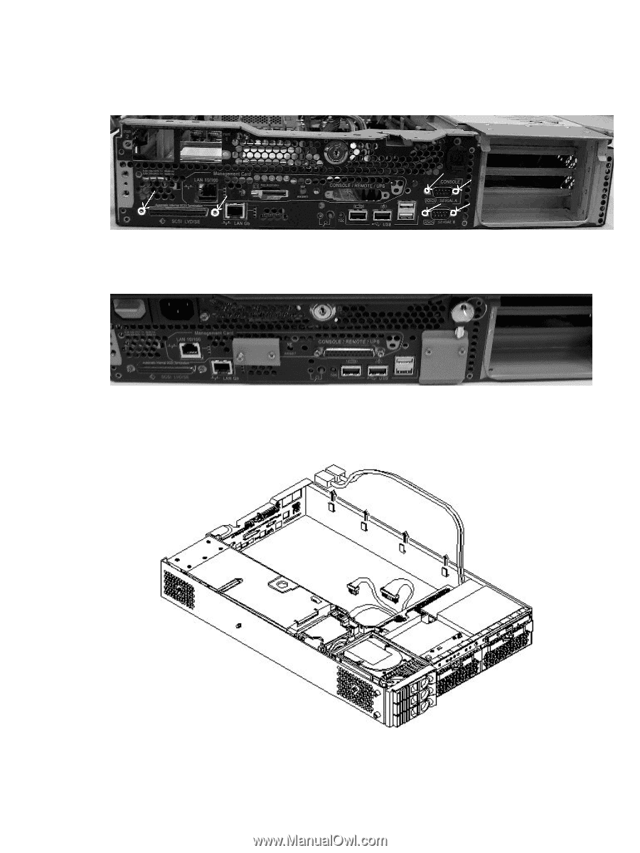
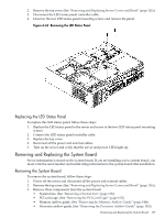
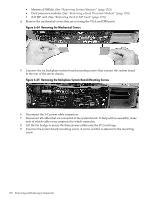
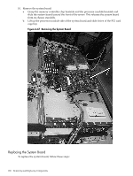
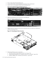
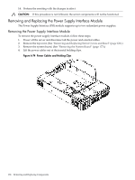
3. Screw in the system board mounting screw. 4. Connect all the cables to their appropriate connectors on the system board. 5. Screw in the six rear backplane system board mounting screws. Figure 6-70 Installing the Rear Panel Mounting Screws 6. Replace the mechanical covers over the VGA and DB9 ports. Figure 6-71 Replacing Mechanical Covers 7. Replace the power connectors in their slots on the back of the server and screw in the power connector mounting screws. Figure 6-72 Reinstalling the Power Connectors 8. Replace the following server components: • iLO MP card. (See "Replacing the iLO MP Card" (page 174)) • Dual processor modules. (See "Installing a Dual Processor Module" (page 160)) • Memory DIMMs. (See "Installing System Memory" (page 152)) 182 Removing and Replacing Components
-
 1
1 -
2
-
3
-
4
-
5
-
6
-
7
-
8
-
9
-
10
-
11
-
12
-
13
-
14
-
15
-
16
-
17
-
18
-
19
-
20
-
21
-
22
-
23
-
24
-
25
-
26
-
27
-
28
-
29
-
30
-
31
-
32
-
33
-
34
-
35
-
36
-
37
-
38
-
39
-
40
-
41
-
42
-
43
-
44
-
45
-
46
-
47
-
48
-
49
-
50
-
51
-
52
-
53
-
54
-
55
-
56
-
57
-
58
-
59
-
60
-
61
-
62
-
63
-
64
-
65
-
66
-
67
-
68
-
69
-
70
-
71
-
72
-
73
-
74
-
75
-
76
-
77
-
78
-
79
-
80
-
81
-
82
-
83
-
84
-
85
-
86
-
87
-
88
-
89
-
90
-
91
-
92
-
93
-
94
-
95
-
96
-
97
-
98
-
99
-
100
-
101
-
102
-
103
-
104
-
105
-
106
-
107
-
108
-
109
-
110
-
111
-
112
-
113
-
114
-
115
-
116
-
117
-
118
-
119
-
120
-
121
-
122
-
123
-
124
-
125
-
126
-
127
-
128
-
129
-
130
-
131
-
132
-
133
-
134
-
135
-
136
-
137
-
138
-
139
-
140
-
141
-
142
-
143
-
144
-
145
-
146
-
147
-
148
-
149
-
150
-
151
-
152
-
153
-
154
-
155
-
156
-
157
-
158
-
159
-
160
-
161
-
162
-
163
-
164
-
165
-
166
-
167
-
168
-
169
-
170
-
171
-
172
-
173
-
174
-
175
-
176
-
 177
177 -
 178
178 -
 179
179 -
 180
180 -
 181
181 -
 182
182 -
 183
183 -
 184
184 -
 185
185 -
 186
186 -
 187
187 -
188
-
189
-
190
-
191
-
192
-
193
-
194
-
195
-
196
-
197
-
198
-
199
-
200
-
201
-
202
-
203
-
204
-
205
-
206
-
207
-
208
-
209
-
210
 |
 |