HP rp3440 User Service Guide, Sixth Edition - HP 9000 rp3410/rp3440 - Page 73
Installation Procedure
 |
View all HP rp3440 manuals
Add to My Manuals
Save this manual to your list of manuals |
Page 73 highlights
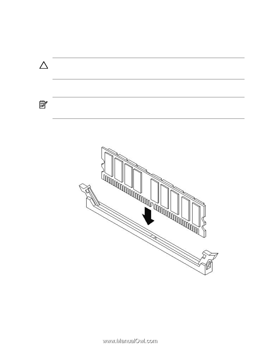
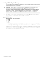
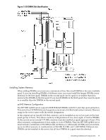
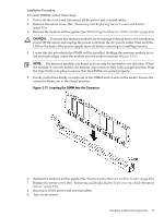
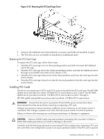
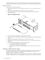
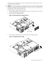
Installation Procedure To install DIMMs, follow these steps: 1. Power off the server and disconnect all the power and external cables. 2. Remove the server cover. (See "Removing and Replacing Server Covers and Bezels" (page 52).) 3. Remove the memory airflow guide. (See "Removing the Memory Airflow Guide" (page 65).) CAUTION: To ensure that memory modules are not damaged during removal or installation, power off the server and unplug the power cord from the AC power outlet. Wait until the LED on the back of the power supply turns off before removing or installing memory. 4. Locate the slot into which the DIMM will be installed. Holding the memory module by its left and right edges, insert the module into the socket connector (Figure 3-31.) NOTE: The memory modules are keyed and can only be inserted in one direction. When the module is correctly seated, the retainer clips return to their fully upright position. Snap the clips firmly into place to ensure that the DIMMs are seated properly. 5. Evenly push down firmly on each end of the DIMM until it seats in the socket. Ensure the extraction levers are in the closed position. Figure 3-31 Inserting the DIMM Into the Connector 6. Replace the memory airflow guide. (See "Replacing the Memory Airflow Guide" (page 66).) 7. Replace the server cover. (See "Removing and Replacing the Top Cover on a Rack-Mounted Server" (page 53).) 8. Reconnect all the power and external cables. 9. Turn on the server. Installing Additional Components 73
-
 1
1 -
2
-
3
-
4
-
5
-
6
-
7
-
8
-
9
-
10
-
11
-
12
-
13
-
14
-
15
-
16
-
17
-
18
-
19
-
20
-
21
-
22
-
23
-
24
-
25
-
26
-
27
-
28
-
29
-
30
-
31
-
32
-
33
-
34
-
35
-
36
-
37
-
38
-
39
-
40
-
41
-
42
-
43
-
44
-
45
-
46
-
47
-
48
-
49
-
50
-
51
-
52
-
53
-
54
-
55
-
56
-
57
-
58
-
59
-
60
-
61
-
62
-
63
-
64
-
65
-
66
-
67
-
 68
68 -
 69
69 -
 70
70 -
 71
71 -
 72
72 -
 73
73 -
 74
74 -
 75
75 -
 76
76 -
 77
77 -
 78
78 -
79
-
80
-
81
-
82
-
83
-
84
-
85
-
86
-
87
-
88
-
89
-
90
-
91
-
92
-
93
-
94
-
95
-
96
-
97
-
98
-
99
-
100
-
101
-
102
-
103
-
104
-
105
-
106
-
107
-
108
-
109
-
110
-
111
-
112
-
113
-
114
-
115
-
116
-
117
-
118
-
119
-
120
-
121
-
122
-
123
-
124
-
125
-
126
-
127
-
128
-
129
-
130
-
131
-
132
-
133
-
134
-
135
-
136
-
137
-
138
-
139
-
140
-
141
-
142
-
143
-
144
-
145
-
146
-
147
-
148
-
149
-
150
-
151
-
152
-
153
-
154
-
155
-
156
-
157
-
158
-
159
-
160
-
161
-
162
-
163
-
164
-
165
-
166
-
167
-
168
-
169
-
170
-
171
-
172
-
173
-
174
-
175
-
176
-
177
-
178
-
179
-
180
-
181
-
182
-
183
-
184
-
185
-
186
-
187
-
188
-
189
-
190
-
191
-
192
-
193
-
194
-
195
-
196
-
197
-
198
-
199
-
200
-
201
-
202
-
203
-
204
-
205
-
206
-
207
-
208
-
209
-
210
 |
 |