HP rp3440 User Service Guide, Sixth Edition - HP 9000 rp3410/rp3440 - Page 38
Powering the Server On and Off, Power States
 |
View all HP rp3440 manuals
Add to My Manuals
Save this manual to your list of manuals |
Page 38 highlights
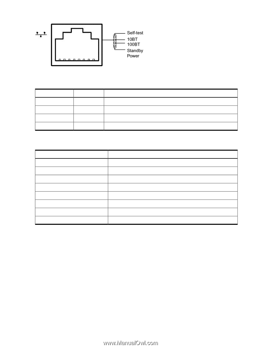
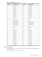
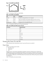
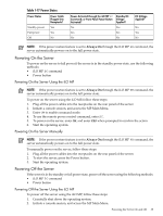
Figure 1-16 iLO MP Card LAN LEDs Table 1-15 lists the iLO MP card LAN LEDs. Table 1-15 iLO MP Card LAN LEDs LED Self-test 10BT 100BT Standby power Color Yellow Green Green Green Description iLO MP is running self-test or error is detected 10BT link established, flashing green 10BT link activity, off no link 100BT link established, flashing green 100BT link activity, off no link Standby power on, off standby power off Table 1-16 lists the iLO MP card LAN connector pinouts. Table 1-16 iLO MP Card LAN Connector Pinouts Pin Number 1 2 3 4 5 6 7 8 Signal Description TXP TXN RXP Not used Not used RXN Not used Not used Powering the Server On and Off This section provides information on how to power the server on and off. Power States The server has three power states: • Standby power • Full power • Off Plug the power cord into the appropriate receptacle on the rear of the server to achieve the standby power state; the front panel Power button is not turned on. Full power occurs when the power cord is plugged into the appropriate receptacle, and either the power is activated through the iLO MP PC command, or the Power button is activated. In the off state, the power cords are not plugged in. Table 1-17 lists the server power states. 38 Overview
-
 1
1 -
2
-
3
-
4
-
5
-
6
-
7
-
8
-
9
-
10
-
11
-
12
-
13
-
14
-
15
-
16
-
17
-
18
-
19
-
20
-
21
-
22
-
23
-
24
-
25
-
26
-
27
-
28
-
29
-
30
-
31
-
32
-
 33
33 -
 34
34 -
 35
35 -
 36
36 -
 37
37 -
 38
38 -
 39
39 -
 40
40 -
 41
41 -
 42
42 -
 43
43 -
44
-
45
-
46
-
47
-
48
-
49
-
50
-
51
-
52
-
53
-
54
-
55
-
56
-
57
-
58
-
59
-
60
-
61
-
62
-
63
-
64
-
65
-
66
-
67
-
68
-
69
-
70
-
71
-
72
-
73
-
74
-
75
-
76
-
77
-
78
-
79
-
80
-
81
-
82
-
83
-
84
-
85
-
86
-
87
-
88
-
89
-
90
-
91
-
92
-
93
-
94
-
95
-
96
-
97
-
98
-
99
-
100
-
101
-
102
-
103
-
104
-
105
-
106
-
107
-
108
-
109
-
110
-
111
-
112
-
113
-
114
-
115
-
116
-
117
-
118
-
119
-
120
-
121
-
122
-
123
-
124
-
125
-
126
-
127
-
128
-
129
-
130
-
131
-
132
-
133
-
134
-
135
-
136
-
137
-
138
-
139
-
140
-
141
-
142
-
143
-
144
-
145
-
146
-
147
-
148
-
149
-
150
-
151
-
152
-
153
-
154
-
155
-
156
-
157
-
158
-
159
-
160
-
161
-
162
-
163
-
164
-
165
-
166
-
167
-
168
-
169
-
170
-
171
-
172
-
173
-
174
-
175
-
176
-
177
-
178
-
179
-
180
-
181
-
182
-
183
-
184
-
185
-
186
-
187
-
188
-
189
-
190
-
191
-
192
-
193
-
194
-
195
-
196
-
197
-
198
-
199
-
200
-
201
-
202
-
203
-
204
-
205
-
206
-
207
-
208
-
209
-
210
 |
 |