HP rp3440 User Service Guide, Sixth Edition - HP 9000 rp3410/rp3440 - Page 160
Installing a Dual Processor Module, Removing and Replacing Server Covers and Bezel
 |
View all HP rp3440 manuals
Add to My Manuals
Save this manual to your list of manuals |
Page 160 highlights
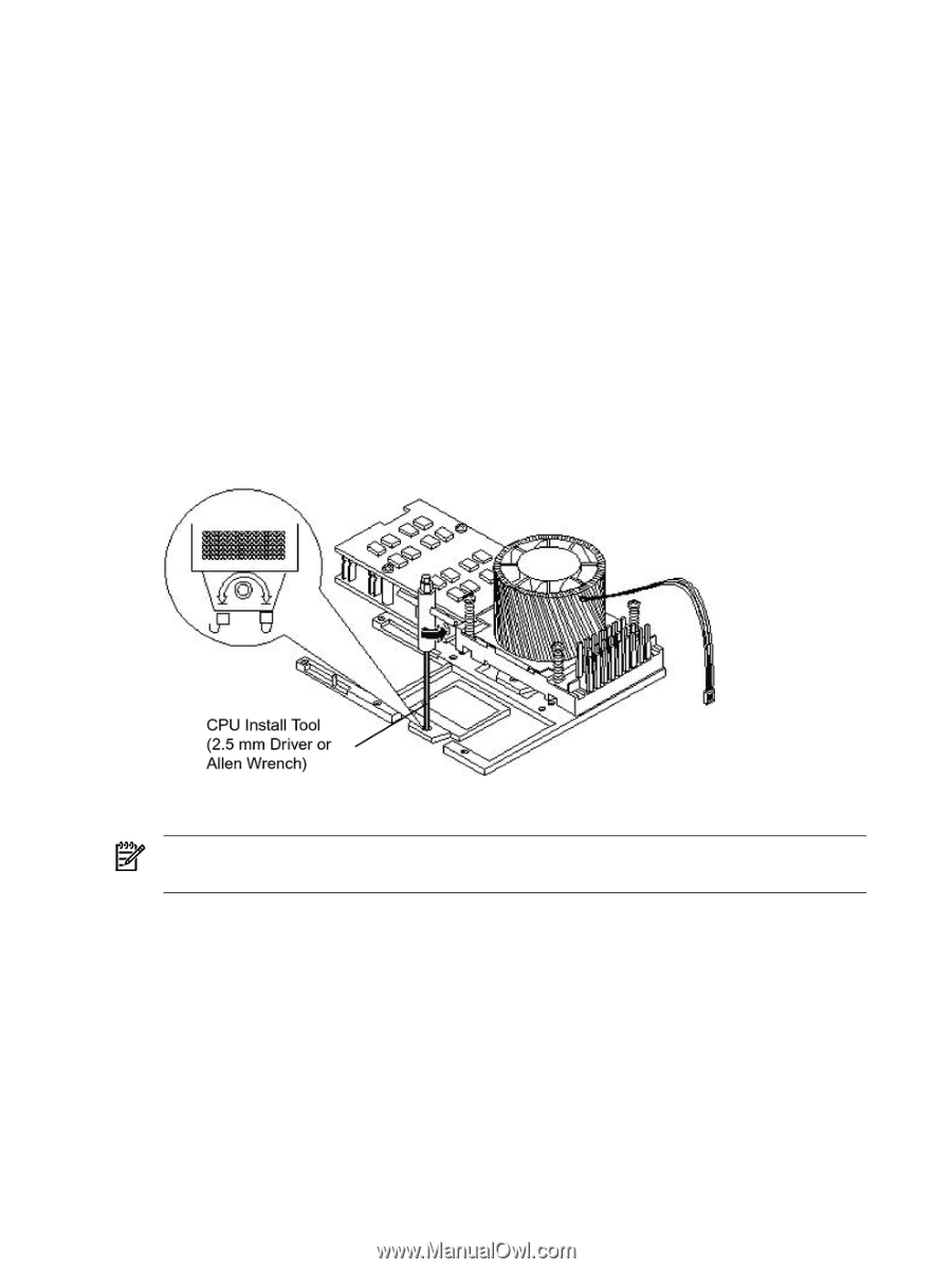
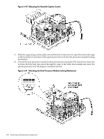
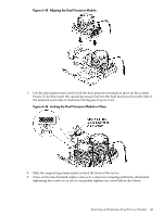
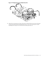
Installing a Dual Processor Module Either one or two dual processor modules are located on the system board. Module #1 is located to the right of the system board and module #2 (when installed) is located on the left of the system board next to the bridge assembly. In a 1P/1C or 1P/2C configuration, you must install the one dual processor module in the CPU0 socket. Each dual processor module has an associated power pod that is required. To install a dual processor module, follow these steps: 1. Power off the server and disconnect the power and external cables. 2. Remove the top cover. (See "Removing and Replacing Server Covers and Bezel" (page 126).) 3. If you are replacing a dual processor module, remove the old module as described in the previous procedure. 4. Unlock the dual processor module locking mechanism using the CPU install tool. a. Insert the tool into the hole that runs down through the edge of the heatsink. b. Rotate the special processor tool 180 degrees counterclockwise. c. Verify that the dual processor module socket locking mechanism is rotated into the unlocked position (Figure 6-44). Figure 6-44 Unlocking the Dual Processor Module Locking Mechanism 5. Remove any protective packaging from the processor modules. NOTE: Protective covers can be installed to protect connector pins. The covers can be saved for future use. 6. Use the four locator posts on the heatsink and the turbo fan power cable to properly align the fan and dual processor module on the system board (Figure 6-45). The four locator posts fit in the locator holes on the system board processor module mount. The turbo fan power cable must be positioned so that it is located on the side of the heatsink that faces the front of the server. 160 Removing and Replacing Components
-
 1
1 -
2
-
3
-
4
-
5
-
6
-
7
-
8
-
9
-
10
-
11
-
12
-
13
-
14
-
15
-
16
-
17
-
18
-
19
-
20
-
21
-
22
-
23
-
24
-
25
-
26
-
27
-
28
-
29
-
30
-
31
-
32
-
33
-
34
-
35
-
36
-
37
-
38
-
39
-
40
-
41
-
42
-
43
-
44
-
45
-
46
-
47
-
48
-
49
-
50
-
51
-
52
-
53
-
54
-
55
-
56
-
57
-
58
-
59
-
60
-
61
-
62
-
63
-
64
-
65
-
66
-
67
-
68
-
69
-
70
-
71
-
72
-
73
-
74
-
75
-
76
-
77
-
78
-
79
-
80
-
81
-
82
-
83
-
84
-
85
-
86
-
87
-
88
-
89
-
90
-
91
-
92
-
93
-
94
-
95
-
96
-
97
-
98
-
99
-
100
-
101
-
102
-
103
-
104
-
105
-
106
-
107
-
108
-
109
-
110
-
111
-
112
-
113
-
114
-
115
-
116
-
117
-
118
-
119
-
120
-
121
-
122
-
123
-
124
-
125
-
126
-
127
-
128
-
129
-
130
-
131
-
132
-
133
-
134
-
135
-
136
-
137
-
138
-
139
-
140
-
141
-
142
-
143
-
144
-
145
-
146
-
147
-
148
-
149
-
150
-
151
-
152
-
153
-
154
-
 155
155 -
 156
156 -
 157
157 -
 158
158 -
 159
159 -
 160
160 -
 161
161 -
 162
162 -
 163
163 -
 164
164 -
 165
165 -
166
-
167
-
168
-
169
-
170
-
171
-
172
-
173
-
174
-
175
-
176
-
177
-
178
-
179
-
180
-
181
-
182
-
183
-
184
-
185
-
186
-
187
-
188
-
189
-
190
-
191
-
192
-
193
-
194
-
195
-
196
-
197
-
198
-
199
-
200
-
201
-
202
-
203
-
204
-
205
-
206
-
207
-
208
-
209
-
210
 |
 |