HP rp3440 User Service Guide, Sixth Edition - HP 9000 rp3410/rp3440 - Page 147
Opening the Release Clip
 |
View all HP rp3440 manuals
Add to My Manuals
Save this manual to your list of manuals |
Page 147 highlights
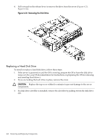
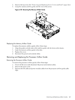
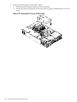
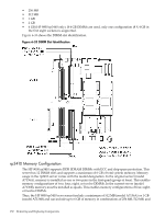
5. Remove the front portion of the airflow guide: a. Remove system fans 1A and 1B. (See "Removing a System Fan" (page 136).) b. Remove the memory airflow guide. (See "Removing the Memory Airflow Guide" (page 144).) c. Rotate the clip clockwise to release the latch. Figure 6-30 Opening the Release Clip d. Disconnect the power cable connected to the guide from the system board by squeezing the clip. e. Lift the front portion of the processor airflow guide out of the server. Figure 6-31 Removing the Front Portion of the Processor Airflow Guide Removing and Replacing Airflow Guides 147
-
 1
1 -
2
-
3
-
4
-
5
-
6
-
7
-
8
-
9
-
10
-
11
-
12
-
13
-
14
-
15
-
16
-
17
-
18
-
19
-
20
-
21
-
22
-
23
-
24
-
25
-
26
-
27
-
28
-
29
-
30
-
31
-
32
-
33
-
34
-
35
-
36
-
37
-
38
-
39
-
40
-
41
-
42
-
43
-
44
-
45
-
46
-
47
-
48
-
49
-
50
-
51
-
52
-
53
-
54
-
55
-
56
-
57
-
58
-
59
-
60
-
61
-
62
-
63
-
64
-
65
-
66
-
67
-
68
-
69
-
70
-
71
-
72
-
73
-
74
-
75
-
76
-
77
-
78
-
79
-
80
-
81
-
82
-
83
-
84
-
85
-
86
-
87
-
88
-
89
-
90
-
91
-
92
-
93
-
94
-
95
-
96
-
97
-
98
-
99
-
100
-
101
-
102
-
103
-
104
-
105
-
106
-
107
-
108
-
109
-
110
-
111
-
112
-
113
-
114
-
115
-
116
-
117
-
118
-
119
-
120
-
121
-
122
-
123
-
124
-
125
-
126
-
127
-
128
-
129
-
130
-
131
-
132
-
133
-
134
-
135
-
136
-
137
-
138
-
139
-
140
-
141
-
 142
142 -
 143
143 -
 144
144 -
 145
145 -
 146
146 -
 147
147 -
 148
148 -
 149
149 -
 150
150 -
 151
151 -
 152
152 -
153
-
154
-
155
-
156
-
157
-
158
-
159
-
160
-
161
-
162
-
163
-
164
-
165
-
166
-
167
-
168
-
169
-
170
-
171
-
172
-
173
-
174
-
175
-
176
-
177
-
178
-
179
-
180
-
181
-
182
-
183
-
184
-
185
-
186
-
187
-
188
-
189
-
190
-
191
-
192
-
193
-
194
-
195
-
196
-
197
-
198
-
199
-
200
-
201
-
202
-
203
-
204
-
205
-
206
-
207
-
208
-
209
-
210
 |
 |
5.
Remove the front portion of the airflow guide:
a.
Remove system fans 1A and 1B. (See
“Removing a System Fan” (page 136)
.)
b.
Remove the memory airflow guide. (See
“Removing the Memory Airflow Guide”
(page 144)
.)
c.
Rotate the clip clockwise to release the latch.
Figure 6-30 Opening the Release Clip
d.
Disconnect the power cable connected to the guide from the system board by squeezing
the clip.
e.
Lift the front portion of the processor airflow guide out of the server.
Figure 6-31 Removing the Front Portion of the Processor Airflow Guide
Removing and Replacing Airflow Guides
147