HP rp3440 User Service Guide, Sixth Edition - HP 9000 rp3410/rp3440 - Page 156
Removing the Power Pod Mounting Screws
 |
View all HP rp3440 manuals
Add to My Manuals
Save this manual to your list of manuals |
Page 156 highlights
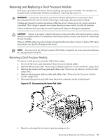
Figure 6-36 Removing the Power Pod Mounting Screws 7. Slide the power pod toward the rear of the system board so that the power pod connector disconnects from its connector on the dual processor module (Figure 6-37. Figure 6-37 Disconnecting the Power Pod From the Dual Processor Module 8. Lift the power pod up and out of the chassis (Figure 6-38). Place the power pod into an antistatic container. 156 Removing and Replacing Components
-
 1
1 -
2
-
3
-
4
-
5
-
6
-
7
-
8
-
9
-
10
-
11
-
12
-
13
-
14
-
15
-
16
-
17
-
18
-
19
-
20
-
21
-
22
-
23
-
24
-
25
-
26
-
27
-
28
-
29
-
30
-
31
-
32
-
33
-
34
-
35
-
36
-
37
-
38
-
39
-
40
-
41
-
42
-
43
-
44
-
45
-
46
-
47
-
48
-
49
-
50
-
51
-
52
-
53
-
54
-
55
-
56
-
57
-
58
-
59
-
60
-
61
-
62
-
63
-
64
-
65
-
66
-
67
-
68
-
69
-
70
-
71
-
72
-
73
-
74
-
75
-
76
-
77
-
78
-
79
-
80
-
81
-
82
-
83
-
84
-
85
-
86
-
87
-
88
-
89
-
90
-
91
-
92
-
93
-
94
-
95
-
96
-
97
-
98
-
99
-
100
-
101
-
102
-
103
-
104
-
105
-
106
-
107
-
108
-
109
-
110
-
111
-
112
-
113
-
114
-
115
-
116
-
117
-
118
-
119
-
120
-
121
-
122
-
123
-
124
-
125
-
126
-
127
-
128
-
129
-
130
-
131
-
132
-
133
-
134
-
135
-
136
-
137
-
138
-
139
-
140
-
141
-
142
-
143
-
144
-
145
-
146
-
147
-
148
-
149
-
150
-
 151
151 -
 152
152 -
 153
153 -
 154
154 -
 155
155 -
 156
156 -
 157
157 -
 158
158 -
 159
159 -
 160
160 -
 161
161 -
162
-
163
-
164
-
165
-
166
-
167
-
168
-
169
-
170
-
171
-
172
-
173
-
174
-
175
-
176
-
177
-
178
-
179
-
180
-
181
-
182
-
183
-
184
-
185
-
186
-
187
-
188
-
189
-
190
-
191
-
192
-
193
-
194
-
195
-
196
-
197
-
198
-
199
-
200
-
201
-
202
-
203
-
204
-
205
-
206
-
207
-
208
-
209
-
210
 |
 |

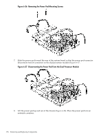
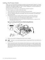
Figure 6-36 Removing the Power Pod Mounting Screws
7.
Slide the power pod toward the rear of the system board so that the power pod connector
disconnects from its connector on the dual processor module (
Figure 6-37
.
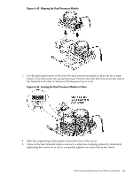
Figure 6-37 Disconnecting the Power Pod From the Dual Processor Module
8.
Lift the power pod up and out of the chassis (
Figure 6-38
). Place the power pod into an
antistatic container.
156
Removing and Replacing Components