HP rp3440 User Service Guide, Sixth Edition - HP 9000 rp3410/rp3440 - Page 183
Removing the PCI Card Cage Replacing the Processor Airflow Guide
 |
View all HP rp3440 manuals
Add to My Manuals
Save this manual to your list of manuals |
Page 183 highlights
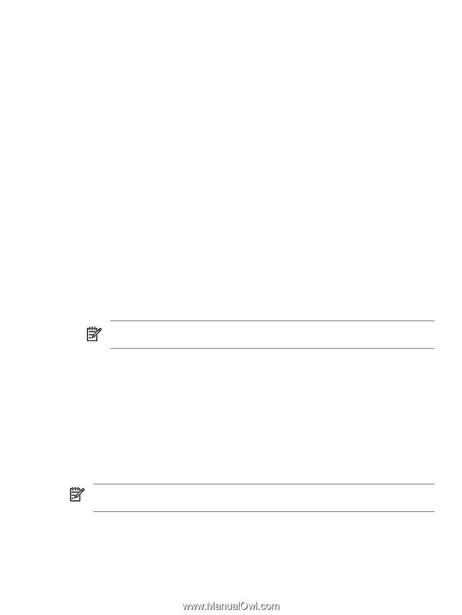
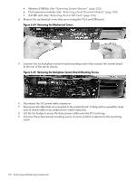
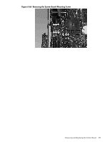
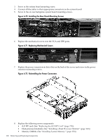
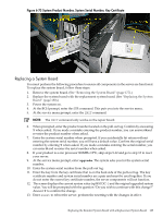
• Processor airflow guide. (See "Replacing the Processor Airflow Guide" (page 148)) • Memory airflow guide. (See "Replacing the Memory Airflow Guide" (page 145)) • PCI card cage. (See "Removing the PCI Card Cage" (page 167)) • System fans. (See "Replacing a System Fan" (page 138)) 9. Replace the top cover. 10. Reconnect all the power and external cables and turn on the server. 11. If you have installed a new system board, you must write the serial number and model string data to the new system board. To write the server information to the new system board, follow these steps: a. Locate the system serial number and note it for use in the following steps. The system serial number is found in two places: • On the left of the front bezel, but to the right of the disk drives, locate the pull tab and extend the tab from the server to display product information. A label containing the system serial number is attached to the pull tab. (Figure 6-73 (page 185)) • A label containing the system serial number is located on the right side of the chassis, as you face the server. b. Monitor server startup on a terminal. At the BCH prompt, enter the SER command to call up the service menu. (For additional information about the BCH, see Appendix B (page 199).) c. At the service menu prompt, enter the INIT command to enter original product number and system serial number. d. When prompted to change, enter the product number that is on the pull tab and confirm by entering Y when prompted. e. When prompted, enter the system serial number. f. When prompted, enter Y to confirm the change. NOTE: If your product is a base system that is one processor 800mhz CPU, skip steps g-j and go to step k to reset the server. g. Enter the upgrade command at the service menu prompt. You will be asked for the system serial number. h. Enter the same system serial number as you previously entered from the pull-out tag. i. Enter the key from the key certificate that is on the back of the pull-out tag. The key certificate number must be the number that applies to this system serial number or all the system components will not be enabled. A current system value displays (rp3410 DC--) with the upgraded system value (the original value). The following prompt displays: Do you wish to continue with the change? j. Enter Y to continue with the change. k. Enter the RESET command to reset the server with the changes in effect. NOTE: If you performed an upgrade, the certificate shows a new key and model number to be used 12. Verify the system board replacement and operation by using the system utilities. (For additional information, see Appendix B (page 199) or the HP Integrity and HP 9000 iLO MP Operations Guide.) • Use the iLO MP commands to verify operation. • Use the BCH commands to verify operation. Removing and Replacing the System Board 183
-
 1
1 -
2
-
3
-
4
-
5
-
6
-
7
-
8
-
9
-
10
-
11
-
12
-
13
-
14
-
15
-
16
-
17
-
18
-
19
-
20
-
21
-
22
-
23
-
24
-
25
-
26
-
27
-
28
-
29
-
30
-
31
-
32
-
33
-
34
-
35
-
36
-
37
-
38
-
39
-
40
-
41
-
42
-
43
-
44
-
45
-
46
-
47
-
48
-
49
-
50
-
51
-
52
-
53
-
54
-
55
-
56
-
57
-
58
-
59
-
60
-
61
-
62
-
63
-
64
-
65
-
66
-
67
-
68
-
69
-
70
-
71
-
72
-
73
-
74
-
75
-
76
-
77
-
78
-
79
-
80
-
81
-
82
-
83
-
84
-
85
-
86
-
87
-
88
-
89
-
90
-
91
-
92
-
93
-
94
-
95
-
96
-
97
-
98
-
99
-
100
-
101
-
102
-
103
-
104
-
105
-
106
-
107
-
108
-
109
-
110
-
111
-
112
-
113
-
114
-
115
-
116
-
117
-
118
-
119
-
120
-
121
-
122
-
123
-
124
-
125
-
126
-
127
-
128
-
129
-
130
-
131
-
132
-
133
-
134
-
135
-
136
-
137
-
138
-
139
-
140
-
141
-
142
-
143
-
144
-
145
-
146
-
147
-
148
-
149
-
150
-
151
-
152
-
153
-
154
-
155
-
156
-
157
-
158
-
159
-
160
-
161
-
162
-
163
-
164
-
165
-
166
-
167
-
168
-
169
-
170
-
171
-
172
-
173
-
174
-
175
-
176
-
177
-
 178
178 -
 179
179 -
 180
180 -
 181
181 -
 182
182 -
 183
183 -
 184
184 -
 185
185 -
 186
186 -
 187
187 -
 188
188 -
189
-
190
-
191
-
192
-
193
-
194
-
195
-
196
-
197
-
198
-
199
-
200
-
201
-
202
-
203
-
204
-
205
-
206
-
207
-
208
-
209
-
210
 |
 |