HP rp3440 User Service Guide, Sixth Edition - HP 9000 rp3410/rp3440 - Page 123
Removing and Replacing Components, Safety Information, Required Service Tools
 |
View all HP rp3440 manuals
Add to My Manuals
Save this manual to your list of manuals |
Page 123 highlights
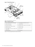
6 Removing and Replacing Components This chapter describes how to remove and replace hardware in HP 9000 rp3410 and rp3440 servers. CAUTION: Use care to prevent injury and equipment damage when performing these procedures. Voltages can be present within the server. Many assemblies are sensitive to damage by electrostatic discharge. Safety Information To ensure safe handling of components, prevent personal injury, and prevent damage to the server, follow the procedures listed below: • If removing or installing a hot-swap or hot-plug item, follow the instructions provided in this guide. • If installing a hot-swappable item when power is applied (fans are running), reinstall the server cover immediately to prevent overheating. • If installing an assembly that is not hot-swappable, disconnect the power cables from the server external power connectors. WARNING! Ensure that the server is powered off and all the power sources have been disconnected from the server before working with the server. Voltages are present at various locations within the server whenever an AC power source is connected. This voltage is present even when the main power switch is in the off position. Failure to observe this warning can result in personal injury or damage to equipment. • Do not wear loose clothing that can snag or catch on the server or on other items. • Do not wear clothing subject to static charge build-up, such as wool or synthetic materials. • If installing an internal assembly, wear an antistatic wrist strap and use a grounding mat, such as those included in the Electrically Conductive Field Service Grounding Kit (HP 9300-1155). • Handle accessory boards and components by the edges only. Do not touch any metal-edge connectors or any electrical components on accessory boards. Required Service Tools Service of this product may require one or more of the following tools: • Electrically Conductive Field Service Kit (HP part number 9300-1155) • 1/4 inch flat blade screwdriver • ACX-15 Torx screwdriver • Special processor tool kit (HP part number 5069-5441) Location of Internal Components and Connectors Figure 6-1 shows the internal physical layout of the server. Safety Information 123
-
 1
1 -
2
-
3
-
4
-
5
-
6
-
7
-
8
-
9
-
10
-
11
-
12
-
13
-
14
-
15
-
16
-
17
-
18
-
19
-
20
-
21
-
22
-
23
-
24
-
25
-
26
-
27
-
28
-
29
-
30
-
31
-
32
-
33
-
34
-
35
-
36
-
37
-
38
-
39
-
40
-
41
-
42
-
43
-
44
-
45
-
46
-
47
-
48
-
49
-
50
-
51
-
52
-
53
-
54
-
55
-
56
-
57
-
58
-
59
-
60
-
61
-
62
-
63
-
64
-
65
-
66
-
67
-
68
-
69
-
70
-
71
-
72
-
73
-
74
-
75
-
76
-
77
-
78
-
79
-
80
-
81
-
82
-
83
-
84
-
85
-
86
-
87
-
88
-
89
-
90
-
91
-
92
-
93
-
94
-
95
-
96
-
97
-
98
-
99
-
100
-
101
-
102
-
103
-
104
-
105
-
106
-
107
-
108
-
109
-
110
-
111
-
112
-
113
-
114
-
115
-
116
-
117
-
 118
118 -
 119
119 -
 120
120 -
 121
121 -
 122
122 -
 123
123 -
 124
124 -
 125
125 -
 126
126 -
 127
127 -
 128
128 -
129
-
130
-
131
-
132
-
133
-
134
-
135
-
136
-
137
-
138
-
139
-
140
-
141
-
142
-
143
-
144
-
145
-
146
-
147
-
148
-
149
-
150
-
151
-
152
-
153
-
154
-
155
-
156
-
157
-
158
-
159
-
160
-
161
-
162
-
163
-
164
-
165
-
166
-
167
-
168
-
169
-
170
-
171
-
172
-
173
-
174
-
175
-
176
-
177
-
178
-
179
-
180
-
181
-
182
-
183
-
184
-
185
-
186
-
187
-
188
-
189
-
190
-
191
-
192
-
193
-
194
-
195
-
196
-
197
-
198
-
199
-
200
-
201
-
202
-
203
-
204
-
205
-
206
-
207
-
208
-
209
-
210
 |
 |