HP rp3440 User Service Guide, Sixth Edition - HP 9000 rp3410/rp3440 - Page 144
Removing and Replacing Airflow Guides, Removing and Replacing the Memory Airflow Guide, Removing the Memory Airflow Guide
 |
View all HP rp3440 manuals
Add to My Manuals
Save this manual to your list of manuals |
Page 144 highlights
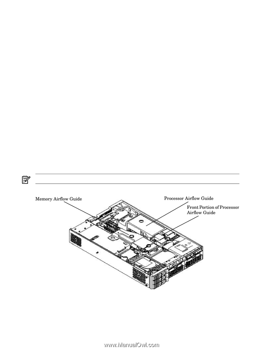
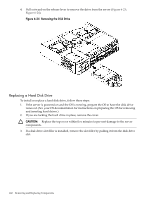
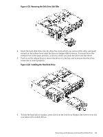
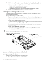
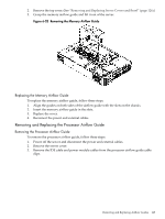
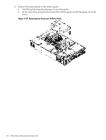
7. Verify the drive replacement and operation by using the system utilities. (For additional information, see Appendix B (page 199) or the HP Integrity and HP 9000 iLO MP Operations Guide.) • Use the iLO MP commands to verify operation. • Use the BCH commands to verify operation. • Use diagnostics provided by the ODE to exercise the newly installed module. 8. Reset the server to the BCH Service Menu to rescan the hard drives. Removing and Replacing Airflow Guides To upgrade, remove, or replace most server components, you must first remove the airflow guides from the server chassis. The server has the following airflow guides: • The processor airflow guide ensures that the proper volume of air for cooling the processor module power pods, processor modules, and voltage regulator modules flows over these components. You must remove the processor airflow guide: • If it is damaged to the point that airflow across the dual processor modules is restricted. • To access components under the airflow guide. • The memory airflow guide ensures that the proper volume of air flows over the memory DIMMs to cool them. You must remove the memory airflow guide: • If it is damaged to the point that airflow across the memory DIMMs is restricted. • To access memory DIMMs and sockets. NOTE: Air flows through the server from front to back. Figure 6-27 Airflow Guides Locations Removing and Replacing the Memory Airflow Guide Removing the Memory Airflow Guide To remove the memory airflow guide, follow these steps: 1. Power off the server and disconnect external cables. 144 Removing and Replacing Components
-
 1
1 -
2
-
3
-
4
-
5
-
6
-
7
-
8
-
9
-
10
-
11
-
12
-
13
-
14
-
15
-
16
-
17
-
18
-
19
-
20
-
21
-
22
-
23
-
24
-
25
-
26
-
27
-
28
-
29
-
30
-
31
-
32
-
33
-
34
-
35
-
36
-
37
-
38
-
39
-
40
-
41
-
42
-
43
-
44
-
45
-
46
-
47
-
48
-
49
-
50
-
51
-
52
-
53
-
54
-
55
-
56
-
57
-
58
-
59
-
60
-
61
-
62
-
63
-
64
-
65
-
66
-
67
-
68
-
69
-
70
-
71
-
72
-
73
-
74
-
75
-
76
-
77
-
78
-
79
-
80
-
81
-
82
-
83
-
84
-
85
-
86
-
87
-
88
-
89
-
90
-
91
-
92
-
93
-
94
-
95
-
96
-
97
-
98
-
99
-
100
-
101
-
102
-
103
-
104
-
105
-
106
-
107
-
108
-
109
-
110
-
111
-
112
-
113
-
114
-
115
-
116
-
117
-
118
-
119
-
120
-
121
-
122
-
123
-
124
-
125
-
126
-
127
-
128
-
129
-
130
-
131
-
132
-
133
-
134
-
135
-
136
-
137
-
138
-
 139
139 -
 140
140 -
 141
141 -
 142
142 -
 143
143 -
 144
144 -
 145
145 -
 146
146 -
 147
147 -
 148
148 -
 149
149 -
150
-
151
-
152
-
153
-
154
-
155
-
156
-
157
-
158
-
159
-
160
-
161
-
162
-
163
-
164
-
165
-
166
-
167
-
168
-
169
-
170
-
171
-
172
-
173
-
174
-
175
-
176
-
177
-
178
-
179
-
180
-
181
-
182
-
183
-
184
-
185
-
186
-
187
-
188
-
189
-
190
-
191
-
192
-
193
-
194
-
195
-
196
-
197
-
198
-
199
-
200
-
201
-
202
-
203
-
204
-
205
-
206
-
207
-
208
-
209
-
210
 |
 |