HP rp3440 User Service Guide, Sixth Edition - HP 9000 rp3410/rp3440 - Page 164
Installing the Processor Module Power Pod Mounting Screws, CAUTION
 |
View all HP rp3440 manuals
Add to My Manuals
Save this manual to your list of manuals |
Page 164 highlights
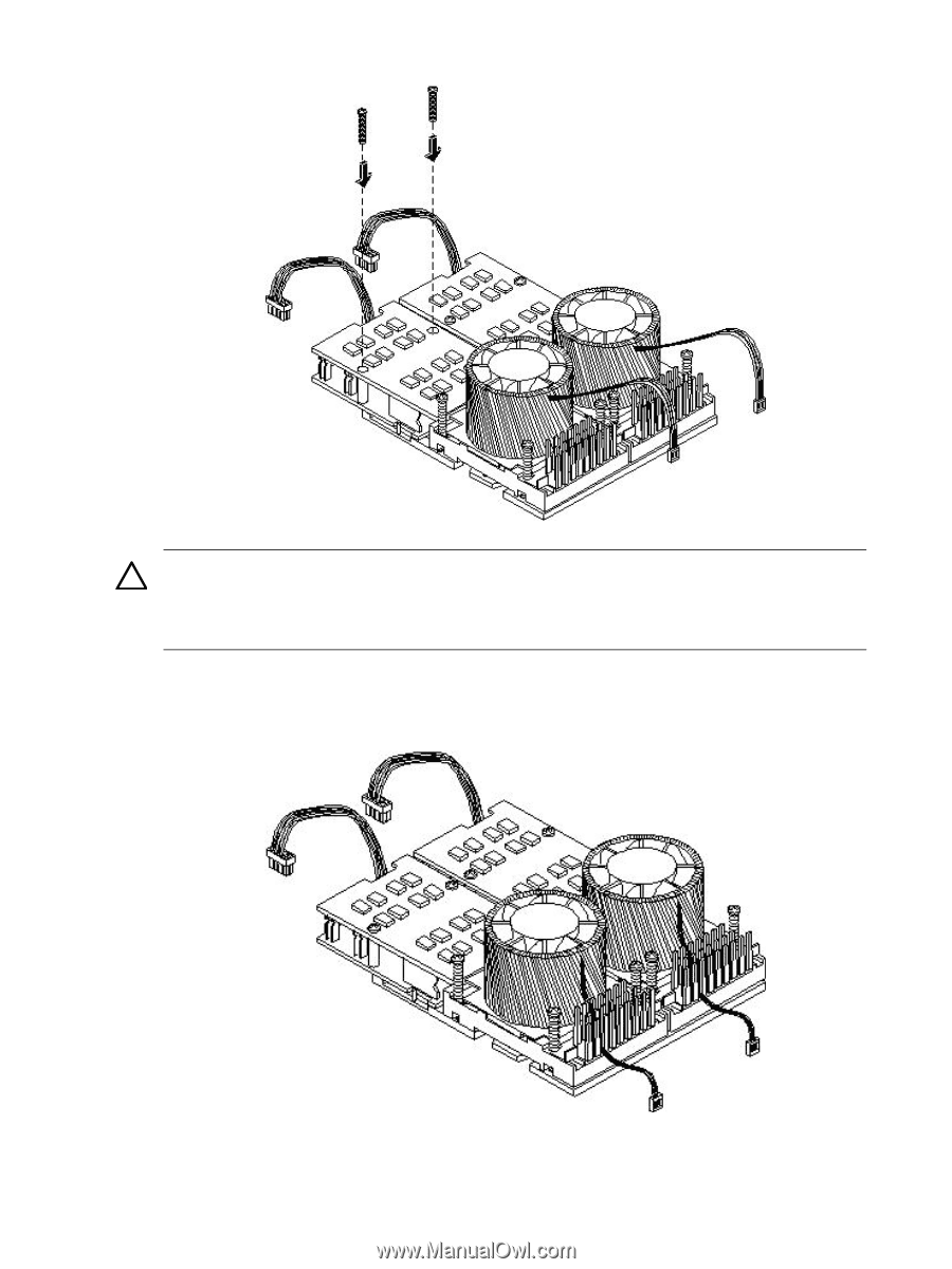
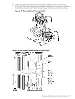
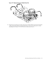
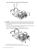
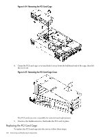
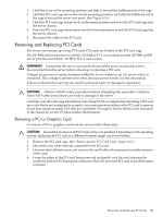
Figure 6-50 Installing the Processor Module Power Pod Mounting Screws CAUTION: Turbo fan power cables can be damaged if pinched between the heatsink posts and the processor airflow guide. Ensure the cables are below the top surface of the heatsink posts before installing the processor airflow guide by routing the cables through the heatsink posts (Figure 6-51). 13. Route the turbo fan power cables through the heatsink posts so the cables will not be pinched when the processor airflow guide is set in place (Figure 6-51). Figure 6-51 Routing the Turbofan Power Cables Through the Heatsink Posts 14. Connect the turbo fan power cable to the system board. 15. Connect the power pod cable to the power connector on the system board. 164 Removing and Replacing Components
-
 1
1 -
2
-
3
-
4
-
5
-
6
-
7
-
8
-
9
-
10
-
11
-
12
-
13
-
14
-
15
-
16
-
17
-
18
-
19
-
20
-
21
-
22
-
23
-
24
-
25
-
26
-
27
-
28
-
29
-
30
-
31
-
32
-
33
-
34
-
35
-
36
-
37
-
38
-
39
-
40
-
41
-
42
-
43
-
44
-
45
-
46
-
47
-
48
-
49
-
50
-
51
-
52
-
53
-
54
-
55
-
56
-
57
-
58
-
59
-
60
-
61
-
62
-
63
-
64
-
65
-
66
-
67
-
68
-
69
-
70
-
71
-
72
-
73
-
74
-
75
-
76
-
77
-
78
-
79
-
80
-
81
-
82
-
83
-
84
-
85
-
86
-
87
-
88
-
89
-
90
-
91
-
92
-
93
-
94
-
95
-
96
-
97
-
98
-
99
-
100
-
101
-
102
-
103
-
104
-
105
-
106
-
107
-
108
-
109
-
110
-
111
-
112
-
113
-
114
-
115
-
116
-
117
-
118
-
119
-
120
-
121
-
122
-
123
-
124
-
125
-
126
-
127
-
128
-
129
-
130
-
131
-
132
-
133
-
134
-
135
-
136
-
137
-
138
-
139
-
140
-
141
-
142
-
143
-
144
-
145
-
146
-
147
-
148
-
149
-
150
-
151
-
152
-
153
-
154
-
155
-
156
-
157
-
158
-
 159
159 -
 160
160 -
 161
161 -
 162
162 -
 163
163 -
 164
164 -
 165
165 -
 166
166 -
 167
167 -
 168
168 -
 169
169 -
170
-
171
-
172
-
173
-
174
-
175
-
176
-
177
-
178
-
179
-
180
-
181
-
182
-
183
-
184
-
185
-
186
-
187
-
188
-
189
-
190
-
191
-
192
-
193
-
194
-
195
-
196
-
197
-
198
-
199
-
200
-
201
-
202
-
203
-
204
-
205
-
206
-
207
-
208
-
209
-
210
 |
 |