HP rp3440 User Service Guide, Sixth Edition - HP 9000 rp3410/rp3440 - Page 129
Removing and Replacing the Front Bezel on a Rack-Mounted Server, Removing the Front Bezel
 |
View all HP rp3440 manuals
Add to My Manuals
Save this manual to your list of manuals |
Page 129 highlights
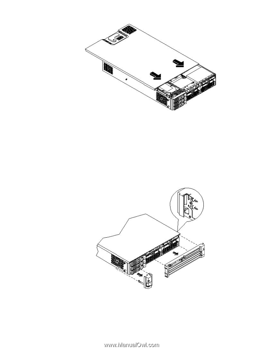
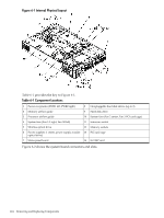
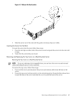
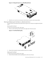
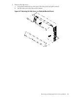
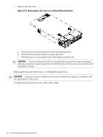
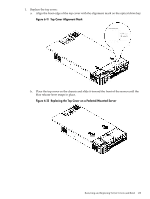
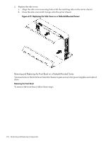
Figure 6-6 Closing the Top Cover on a Rack-Mounted Server 3. Slide the server into the rack enclosure and reconnect the power and external cables. Removing and Replacing the Front Bezel on a Rack-Mounted Server You must remove the front bezel from the chassis to gain access to the power supplies and optical drive. Removing the Front Bezel To remove the front bezel, follow these steps: 1. Press in on the retaining clips located on the right-side of the front panel. Figure 6-7 Front Bezel Retaining Clip 2. Rotate the front panel outward and lift it off the server chassis. Replacing the Front Bezel To replace the front bezel, follow these steps: 1. Insert the bezel latches into the matching slots on the server chassis. Removing and Replacing Server Covers and Bezel 129
-
 1
1 -
2
-
3
-
4
-
5
-
6
-
7
-
8
-
9
-
10
-
11
-
12
-
13
-
14
-
15
-
16
-
17
-
18
-
19
-
20
-
21
-
22
-
23
-
24
-
25
-
26
-
27
-
28
-
29
-
30
-
31
-
32
-
33
-
34
-
35
-
36
-
37
-
38
-
39
-
40
-
41
-
42
-
43
-
44
-
45
-
46
-
47
-
48
-
49
-
50
-
51
-
52
-
53
-
54
-
55
-
56
-
57
-
58
-
59
-
60
-
61
-
62
-
63
-
64
-
65
-
66
-
67
-
68
-
69
-
70
-
71
-
72
-
73
-
74
-
75
-
76
-
77
-
78
-
79
-
80
-
81
-
82
-
83
-
84
-
85
-
86
-
87
-
88
-
89
-
90
-
91
-
92
-
93
-
94
-
95
-
96
-
97
-
98
-
99
-
100
-
101
-
102
-
103
-
104
-
105
-
106
-
107
-
108
-
109
-
110
-
111
-
112
-
113
-
114
-
115
-
116
-
117
-
118
-
119
-
120
-
121
-
122
-
123
-
 124
124 -
 125
125 -
 126
126 -
 127
127 -
 128
128 -
 129
129 -
 130
130 -
 131
131 -
 132
132 -
 133
133 -
 134
134 -
135
-
136
-
137
-
138
-
139
-
140
-
141
-
142
-
143
-
144
-
145
-
146
-
147
-
148
-
149
-
150
-
151
-
152
-
153
-
154
-
155
-
156
-
157
-
158
-
159
-
160
-
161
-
162
-
163
-
164
-
165
-
166
-
167
-
168
-
169
-
170
-
171
-
172
-
173
-
174
-
175
-
176
-
177
-
178
-
179
-
180
-
181
-
182
-
183
-
184
-
185
-
186
-
187
-
188
-
189
-
190
-
191
-
192
-
193
-
194
-
195
-
196
-
197
-
198
-
199
-
200
-
201
-
202
-
203
-
204
-
205
-
206
-
207
-
208
-
209
-
210
 |
 |