HP rp3440 User Service Guide, Sixth Edition - HP 9000 rp3410/rp3440 - Page 82
Power Module Shims, Aligning the Processor Module Power Pod
 |
View all HP rp3440 manuals
Add to My Manuals
Save this manual to your list of manuals |
Page 82 highlights
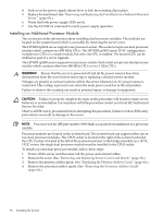
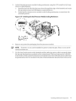
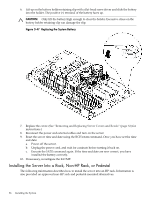
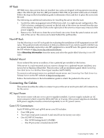
Figure 3-42 Power Module Shims 12. Slide the power pod module on the system board metal mounting bracket so that the power pod module connector connects with its connector on the processor module. Figure 3-43 Aligning the Processor Module Power Pod 13. Align the two mounting screw holes on the power pod module with the screw holes in the shims on the system board metal mounting bracket. Screw in the power pod module mounting screws. (Use the screws removed in step Step 11.) 82 Installing the System
-
 1
1 -
2
-
3
-
4
-
5
-
6
-
7
-
8
-
9
-
10
-
11
-
12
-
13
-
14
-
15
-
16
-
17
-
18
-
19
-
20
-
21
-
22
-
23
-
24
-
25
-
26
-
27
-
28
-
29
-
30
-
31
-
32
-
33
-
34
-
35
-
36
-
37
-
38
-
39
-
40
-
41
-
42
-
43
-
44
-
45
-
46
-
47
-
48
-
49
-
50
-
51
-
52
-
53
-
54
-
55
-
56
-
57
-
58
-
59
-
60
-
61
-
62
-
63
-
64
-
65
-
66
-
67
-
68
-
69
-
70
-
71
-
72
-
73
-
74
-
75
-
76
-
 77
77 -
 78
78 -
 79
79 -
 80
80 -
 81
81 -
 82
82 -
 83
83 -
 84
84 -
 85
85 -
 86
86 -
 87
87 -
88
-
89
-
90
-
91
-
92
-
93
-
94
-
95
-
96
-
97
-
98
-
99
-
100
-
101
-
102
-
103
-
104
-
105
-
106
-
107
-
108
-
109
-
110
-
111
-
112
-
113
-
114
-
115
-
116
-
117
-
118
-
119
-
120
-
121
-
122
-
123
-
124
-
125
-
126
-
127
-
128
-
129
-
130
-
131
-
132
-
133
-
134
-
135
-
136
-
137
-
138
-
139
-
140
-
141
-
142
-
143
-
144
-
145
-
146
-
147
-
148
-
149
-
150
-
151
-
152
-
153
-
154
-
155
-
156
-
157
-
158
-
159
-
160
-
161
-
162
-
163
-
164
-
165
-
166
-
167
-
168
-
169
-
170
-
171
-
172
-
173
-
174
-
175
-
176
-
177
-
178
-
179
-
180
-
181
-
182
-
183
-
184
-
185
-
186
-
187
-
188
-
189
-
190
-
191
-
192
-
193
-
194
-
195
-
196
-
197
-
198
-
199
-
200
-
201
-
202
-
203
-
204
-
205
-
206
-
207
-
208
-
209
-
210
 |
 |

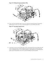
Figure 3-42 Power Module Shims
12.
Slide the power pod module on the system board metal mounting bracket so that the power
pod module connector connects with its connector on the processor module.
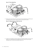
Figure 3-43 Aligning the Processor Module Power Pod
13.
Align the two mounting screw holes on the power pod module with the screw holes in the
shims on the system board metal mounting bracket. Screw in the power pod module
mounting screws. (Use the screws removed in step
Step 11
.)
82
Installing the System