HP rp3440 User Service Guide, Sixth Edition - HP 9000 rp3410/rp3440 - Page 161
Aligning the Dual Processor Module
 |
View all HP rp3440 manuals
Add to My Manuals
Save this manual to your list of manuals |
Page 161 highlights
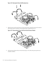
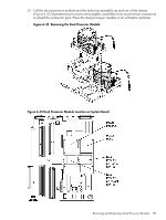
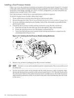
Figure 6-45 Aligning the Dual Processor Module 7. Use the special processor tool to lock the dual processor module in place on the system board. To do this, insert the special processor tool into the hole that runs down the side of the heatsink and rotate it clockwise 180 degrees (Figure 6-46). Figure 6-46 Locking the Dual Processor Module in Place 8. Slide the sequencing retainer plate toward the front of the server. 9. Screw in the four heatsink captive screws in a crisscross torquing pattern by alternately tightening the screws so as not to completely tighten one screw before the others. Removing and Replacing a Dual Processor Module 161
-
 1
1 -
2
-
3
-
4
-
5
-
6
-
7
-
8
-
9
-
10
-
11
-
12
-
13
-
14
-
15
-
16
-
17
-
18
-
19
-
20
-
21
-
22
-
23
-
24
-
25
-
26
-
27
-
28
-
29
-
30
-
31
-
32
-
33
-
34
-
35
-
36
-
37
-
38
-
39
-
40
-
41
-
42
-
43
-
44
-
45
-
46
-
47
-
48
-
49
-
50
-
51
-
52
-
53
-
54
-
55
-
56
-
57
-
58
-
59
-
60
-
61
-
62
-
63
-
64
-
65
-
66
-
67
-
68
-
69
-
70
-
71
-
72
-
73
-
74
-
75
-
76
-
77
-
78
-
79
-
80
-
81
-
82
-
83
-
84
-
85
-
86
-
87
-
88
-
89
-
90
-
91
-
92
-
93
-
94
-
95
-
96
-
97
-
98
-
99
-
100
-
101
-
102
-
103
-
104
-
105
-
106
-
107
-
108
-
109
-
110
-
111
-
112
-
113
-
114
-
115
-
116
-
117
-
118
-
119
-
120
-
121
-
122
-
123
-
124
-
125
-
126
-
127
-
128
-
129
-
130
-
131
-
132
-
133
-
134
-
135
-
136
-
137
-
138
-
139
-
140
-
141
-
142
-
143
-
144
-
145
-
146
-
147
-
148
-
149
-
150
-
151
-
152
-
153
-
154
-
155
-
 156
156 -
 157
157 -
 158
158 -
 159
159 -
 160
160 -
 161
161 -
 162
162 -
 163
163 -
 164
164 -
 165
165 -
 166
166 -
167
-
168
-
169
-
170
-
171
-
172
-
173
-
174
-
175
-
176
-
177
-
178
-
179
-
180
-
181
-
182
-
183
-
184
-
185
-
186
-
187
-
188
-
189
-
190
-
191
-
192
-
193
-
194
-
195
-
196
-
197
-
198
-
199
-
200
-
201
-
202
-
203
-
204
-
205
-
206
-
207
-
208
-
209
-
210
 |
 |
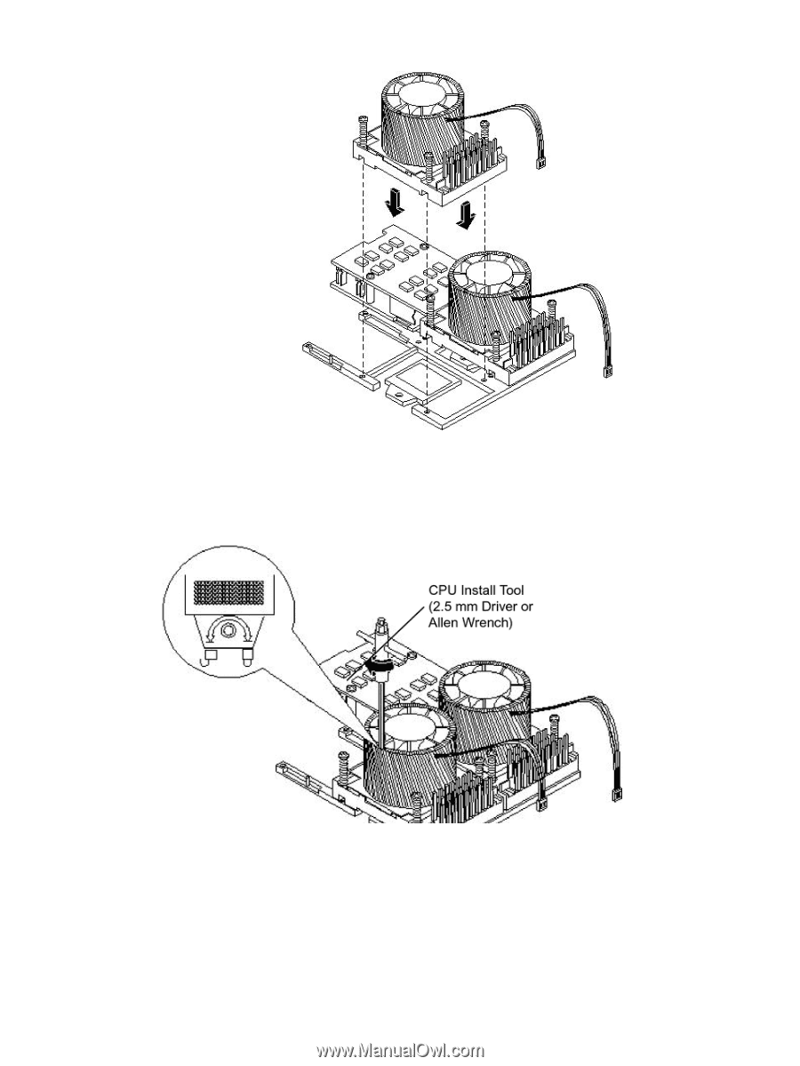
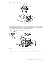
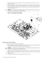
Figure 6-45 Aligning the Dual Processor Module
7.
Use the special processor tool to lock the dual processor module in place on the system
board. To do this, insert the special processor tool into the hole that runs down the side of
the heatsink and rotate it clockwise 180 degrees (
Figure 6-46
).
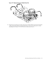
Figure 6-46 Locking the Dual Processor Module in Place
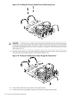
8.
Slide the sequencing retainer plate toward the front of the server.
9.
Screw in the four heatsink captive screws in a crisscross torquing pattern by alternately
tightening the screws so as not to completely tighten one screw before the others.
Removing and Replacing a Dual Processor Module
161