HP rp3440 User Service Guide, Sixth Edition - HP 9000 rp3410/rp3440 - Page 81
Sliding the Sequencing Retainer Plate, Securing the Captive Screws
 |
View all HP rp3440 manuals
Add to My Manuals
Save this manual to your list of manuals |
Page 81 highlights
Figure 3-40 Sliding the Sequencing Retainer Plate 10. Screw in the four heatsink captive screws in a crisscross torquing pattern by alternately tightening the screws so as not to completely tighten one screw before the others. Figure 3-41 Securing the Captive Screws 11. Locate the two power pod module shims on the system board. (On servers delivered with only one dual processor module installed, the power module shims are held in place by screws with plastic spacers over the threads.) Remove the holding screws and discard the plastic spacers. Retain the screws for use when installing the power module. Installing Additional Components 81
-
 1
1 -
2
-
3
-
4
-
5
-
6
-
7
-
8
-
9
-
10
-
11
-
12
-
13
-
14
-
15
-
16
-
17
-
18
-
19
-
20
-
21
-
22
-
23
-
24
-
25
-
26
-
27
-
28
-
29
-
30
-
31
-
32
-
33
-
34
-
35
-
36
-
37
-
38
-
39
-
40
-
41
-
42
-
43
-
44
-
45
-
46
-
47
-
48
-
49
-
50
-
51
-
52
-
53
-
54
-
55
-
56
-
57
-
58
-
59
-
60
-
61
-
62
-
63
-
64
-
65
-
66
-
67
-
68
-
69
-
70
-
71
-
72
-
73
-
74
-
75
-
 76
76 -
 77
77 -
 78
78 -
 79
79 -
 80
80 -
 81
81 -
 82
82 -
 83
83 -
 84
84 -
 85
85 -
 86
86 -
87
-
88
-
89
-
90
-
91
-
92
-
93
-
94
-
95
-
96
-
97
-
98
-
99
-
100
-
101
-
102
-
103
-
104
-
105
-
106
-
107
-
108
-
109
-
110
-
111
-
112
-
113
-
114
-
115
-
116
-
117
-
118
-
119
-
120
-
121
-
122
-
123
-
124
-
125
-
126
-
127
-
128
-
129
-
130
-
131
-
132
-
133
-
134
-
135
-
136
-
137
-
138
-
139
-
140
-
141
-
142
-
143
-
144
-
145
-
146
-
147
-
148
-
149
-
150
-
151
-
152
-
153
-
154
-
155
-
156
-
157
-
158
-
159
-
160
-
161
-
162
-
163
-
164
-
165
-
166
-
167
-
168
-
169
-
170
-
171
-
172
-
173
-
174
-
175
-
176
-
177
-
178
-
179
-
180
-
181
-
182
-
183
-
184
-
185
-
186
-
187
-
188
-
189
-
190
-
191
-
192
-
193
-
194
-
195
-
196
-
197
-
198
-
199
-
200
-
201
-
202
-
203
-
204
-
205
-
206
-
207
-
208
-
209
-
210
 |
 |
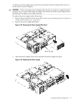
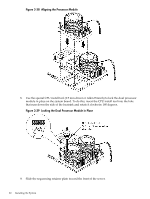
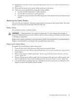
Figure 3-40 Sliding the Sequencing Retainer Plate
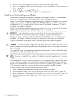
10.
Screw in the four heatsink captive screws in a crisscross torquing pattern by alternately
tightening the screws so as not to completely tighten one screw before the others.
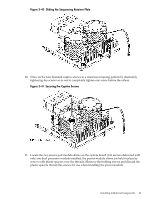
Figure 3-41 Securing the Captive Screws
11.
Locate the two power pod module shims on the system board. (On servers delivered with
only one dual processor module installed, the power module shims are held in place by
screws with plastic spacers over the threads.) Remove the holding screws and discard the
plastic spacers. Retain the screws for use when installing the power module.
Installing Additional Components
81