HP rp3440 User Service Guide, Sixth Edition - HP 9000 rp3410/rp3440 - Page 125
System Board Connectors and Slots, Table 6-2 Connector Locations, Table 6-2,
 |
View all HP rp3440 manuals
Add to My Manuals
Save this manual to your list of manuals |
Page 125 highlights
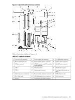
Figure 6-2 System Board Connectors and Slots Table 6-2 provides the key to Figure 6-2. Table 6-2 Connector Locations 1 External SCSI connector 2 SCSI connectors A & B 3 CPU power pods 4 CPU 1 5 CPU 0 6 Turbo fan power connectors 7 Five VRM cards 8 Battery 9 Power supply fan connector 17 PCI backplane connector 10 Power module power connector 18 Optical drive connector 11 HP ZX1 memory and I/O controller 19 iLO MP card connector (under heatsink) 12 Memory sockets 20 HP ZX1 I/O adapter 13 Status panel connector 21 Serial ports (2) (factory use only) 14 Power module auxiliary connector 22 USB connectors (4) 15 SCSI backplane power connector 23 LAN connector 16 PCI/memory fan cable connector Location of Internal Components and Connectors 125
-
 1
1 -
2
-
3
-
4
-
5
-
6
-
7
-
8
-
9
-
10
-
11
-
12
-
13
-
14
-
15
-
16
-
17
-
18
-
19
-
20
-
21
-
22
-
23
-
24
-
25
-
26
-
27
-
28
-
29
-
30
-
31
-
32
-
33
-
34
-
35
-
36
-
37
-
38
-
39
-
40
-
41
-
42
-
43
-
44
-
45
-
46
-
47
-
48
-
49
-
50
-
51
-
52
-
53
-
54
-
55
-
56
-
57
-
58
-
59
-
60
-
61
-
62
-
63
-
64
-
65
-
66
-
67
-
68
-
69
-
70
-
71
-
72
-
73
-
74
-
75
-
76
-
77
-
78
-
79
-
80
-
81
-
82
-
83
-
84
-
85
-
86
-
87
-
88
-
89
-
90
-
91
-
92
-
93
-
94
-
95
-
96
-
97
-
98
-
99
-
100
-
101
-
102
-
103
-
104
-
105
-
106
-
107
-
108
-
109
-
110
-
111
-
112
-
113
-
114
-
115
-
116
-
117
-
118
-
119
-
 120
120 -
 121
121 -
 122
122 -
 123
123 -
 124
124 -
 125
125 -
 126
126 -
 127
127 -
 128
128 -
 129
129 -
 130
130 -
131
-
132
-
133
-
134
-
135
-
136
-
137
-
138
-
139
-
140
-
141
-
142
-
143
-
144
-
145
-
146
-
147
-
148
-
149
-
150
-
151
-
152
-
153
-
154
-
155
-
156
-
157
-
158
-
159
-
160
-
161
-
162
-
163
-
164
-
165
-
166
-
167
-
168
-
169
-
170
-
171
-
172
-
173
-
174
-
175
-
176
-
177
-
178
-
179
-
180
-
181
-
182
-
183
-
184
-
185
-
186
-
187
-
188
-
189
-
190
-
191
-
192
-
193
-
194
-
195
-
196
-
197
-
198
-
199
-
200
-
201
-
202
-
203
-
204
-
205
-
206
-
207
-
208
-
209
-
210
 |
 |
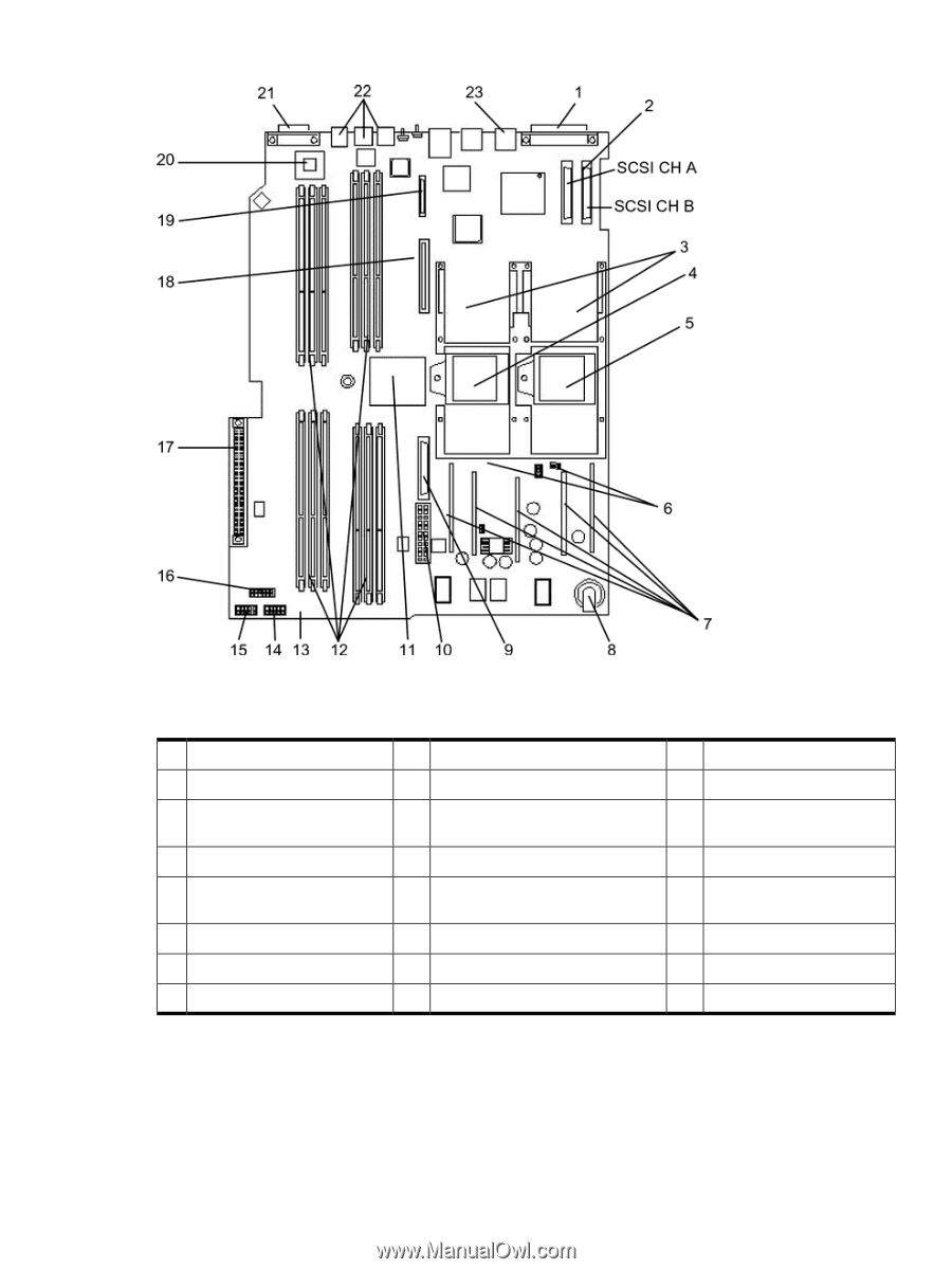
Figure 6-2 System Board Connectors and Slots
Table 6-2
provides the key to
Figure 6-2
.
Table 6-2 Connector Locations
PCI backplane connector
17
Power supply fan connector
9
External SCSI connector
1
Optical drive connector
18
Power module power connector
10
SCSI connectors A & B
2
iLO MP card connector
19
HP ZX1 memory and I/O controller
(under heatsink)
11
CPU power pods
3
HP ZX1 I/O adapter
20
Memory sockets
12
CPU 1
4
Serial ports (2) (factory use
only)
21
Status panel connector
13
CPU 0
5
USB connectors (4)
22
Power module auxiliary connector
14
Turbo fan power connectors
6
LAN connector
23
SCSI backplane power connector
15
Five VRM cards
7
PCI/memory fan cable connector
16
Battery
8
Location of Internal Components and Connectors
125