HP rp3440 User Service Guide, Sixth Edition - HP 9000 rp3410/rp3440 - Page 27
Chip Spare Functionality, Serial Presence Detect, I/O Bus Interface
 |
View all HP rp3440 manuals
Add to My Manuals
Save this manual to your list of manuals |
Page 27 highlights
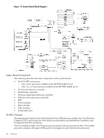
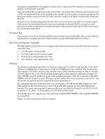
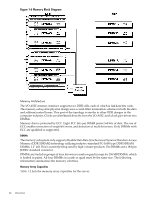
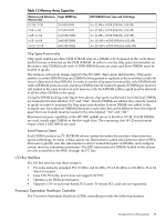
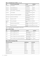
Table 1-2 Memory Array Capacities Minimum and Maximum Single DIMM Size Memory Size 0.5 GB / 3 GB 256 MB DIMM 2 GB / 6 GB 512 MB DIMM 4 GB / 12 GB 1024 MB DIMM 8 GB / 24 GB 2048 MB DIMM 16 GB / 32 GB 4096 MB DIMM DDR SDRAM Count, Type and Technology 18 x 32 MB x 4 DDR SDRAMs (128 MB) 36 x 32 MB x 4 DDR SDRAMs (128 MB) 36 x 64 MB x 4 DDR SDRAMs (256 MB) 36 x 128 MB x 4 DDR SDRAMs (512 MB) 36 x 256 MB x 4 DDR SDRAMs (1024 MB) Chip Spare Functionality Chip spare enables an entire DDR SDRAM chip on a DIMM to be bypassed in the event that a multi-bit error is detected on the DDR SDRAM. In order to use the chip spare functionality on the server, only DIMMs built with ×4 DDR SDRAM parts are used, and these DIMMs must be loaded in quads. The memory subsystem design supports the I/O ASIC chip's spare functionality. Chip spare enables an entire SDRAM chip on a DIMM to be bypassed or replaced in the event that a multi-bit error is detected on that SDRAM. In order to use the chip spare functionality, only DIMMs built with x4 SDRAM parts are used, and these DIMMs must be loaded in quads (2 DIMMs per memory cell, loaded in the same location in each memory cell). Each DIMM within a quad must be identical to all the other DIMMs in the quad. Using the DIMM loading order figure from above, chip spare is achieved if four identical DIMMs are loaded in the slots labeled "1st" and "2nd." If more DIMMs are added, they must be loaded in quads in order to maintain the chip spare functionality. If more DIMMs are added to the example case, four identical DIMMs (identical to each other, but can be different from the original quad that was loaded) must be loaded in the slots labeled "3rd" and "4th." Maximum memory capability of the HP 9000 rp3440 server is 24 GB or 32 GB. If 4 GB DIMMs are used, install eight DIMMs in the first eight slots. The remaining slots (9-12) must remain empty when 4 GB DIMMs are used. Serial Presence Detect Each DIMM contains an I2C EEPROM whose content describes the module's characteristics: speed, technology, revision, vendor, and so on. This feature is called serial presence detect (SPD). Firmware typically uses this information to detect unmatched pairs of DIMMs, and configure certain memory subsystem parameters. The SPD information for DIMMs loaded in the system are also accessible to the BMC through the I2C bus. I/O Bus Interface The I/O bus interface has these features: • Provides industry standard PCI 33 MHz and 66 MHz, PCI-X 66 MHz to 133 MHz, 32 or 64 data bit support. • Uses 3.3V PCI only, and it does not support 5V PCI. • Optimizes for DMA performance. • Supports 3.3V or universal-keyed PCI cards. 5V-keyed PCI cards are not supported. Processor Dependent Hardware Controller The Processor Dependent Hardware (PDH) controller provides the following features. Detailed Server Description 27
-
 1
1 -
2
-
3
-
4
-
5
-
6
-
7
-
8
-
9
-
10
-
11
-
12
-
13
-
14
-
15
-
16
-
17
-
18
-
19
-
20
-
21
-
 22
22 -
 23
23 -
 24
24 -
 25
25 -
 26
26 -
 27
27 -
 28
28 -
 29
29 -
 30
30 -
 31
31 -
 32
32 -
33
-
34
-
35
-
36
-
37
-
38
-
39
-
40
-
41
-
42
-
43
-
44
-
45
-
46
-
47
-
48
-
49
-
50
-
51
-
52
-
53
-
54
-
55
-
56
-
57
-
58
-
59
-
60
-
61
-
62
-
63
-
64
-
65
-
66
-
67
-
68
-
69
-
70
-
71
-
72
-
73
-
74
-
75
-
76
-
77
-
78
-
79
-
80
-
81
-
82
-
83
-
84
-
85
-
86
-
87
-
88
-
89
-
90
-
91
-
92
-
93
-
94
-
95
-
96
-
97
-
98
-
99
-
100
-
101
-
102
-
103
-
104
-
105
-
106
-
107
-
108
-
109
-
110
-
111
-
112
-
113
-
114
-
115
-
116
-
117
-
118
-
119
-
120
-
121
-
122
-
123
-
124
-
125
-
126
-
127
-
128
-
129
-
130
-
131
-
132
-
133
-
134
-
135
-
136
-
137
-
138
-
139
-
140
-
141
-
142
-
143
-
144
-
145
-
146
-
147
-
148
-
149
-
150
-
151
-
152
-
153
-
154
-
155
-
156
-
157
-
158
-
159
-
160
-
161
-
162
-
163
-
164
-
165
-
166
-
167
-
168
-
169
-
170
-
171
-
172
-
173
-
174
-
175
-
176
-
177
-
178
-
179
-
180
-
181
-
182
-
183
-
184
-
185
-
186
-
187
-
188
-
189
-
190
-
191
-
192
-
193
-
194
-
195
-
196
-
197
-
198
-
199
-
200
-
201
-
202
-
203
-
204
-
205
-
206
-
207
-
208
-
209
-
210
 |
 |